Inspection and Repair
Perform the necessary adjustments, repairs, and part replacements if excessive wear or damage is discovered during inspection.
It is important that electrical components be kept clean and dry at all times.
Always visibly check the fusible links, the fuses, and the indicator lights for damage as the first step in the inspection and repair procedure.
Armature
Commutator Face
- Check the commutator face for roughness.
- If necessary, dress the commutator face with fine sandpaper (#500 or #600).
- Be absolutely sure that there are no metal filings in the segment gaps.
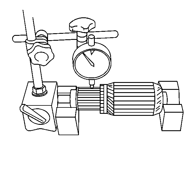
Commutator Run-Out
- Mount the armature assembly on V-blocks.
- Use a dial indicator to measure the commutator run-out. If the run-out is greater than the specified standard but less than the specified limit, the commutator may be turned on a lathe to correct it. If the run-out exceeds the specified limit, the armature assembly must be replaced.
Commutator Run-Out
The standard is 0.06 mm (0.002 in) or less. The
limit is 0.1 mm (0.004 in).
Commutator Segment Groove Depth
- Use the V-blocks and the dial indicator to measure the depth of each of the commutator segment grooves.
- Replace the armature assembly if the commutator segment groove depth is less than the specified limit.
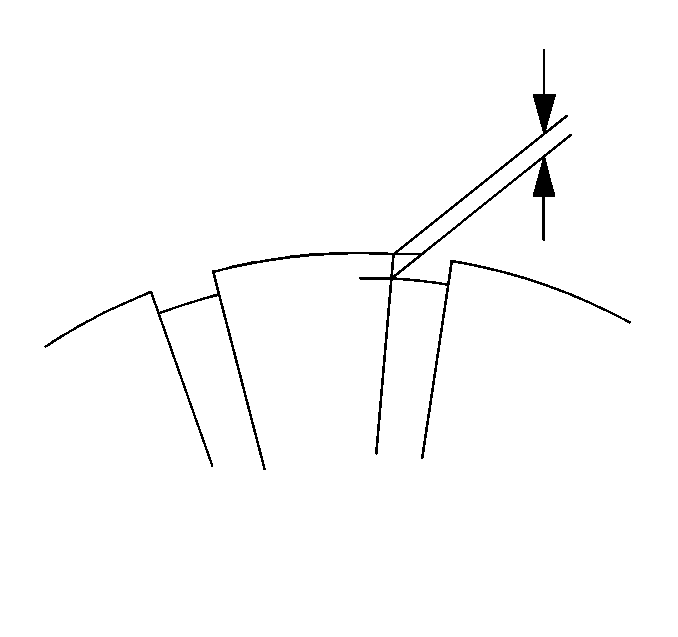
Commutator Segment Groove Depth
The standard is 0.5-0.8 mm (0.020-0.031 in)
or less. The limit is 0.2 mm (0.008 in).
Commutator Outside Diameter
- Use a vernier caliper to measure the commutator outside diameter.
- If the commutator outside diameter is less than the specified standard but greater than the specified limit, the commutator may be turned on a lathe to correct it.
- Replace the armature assembly if the commutator outside diameter is less than the specified limit.
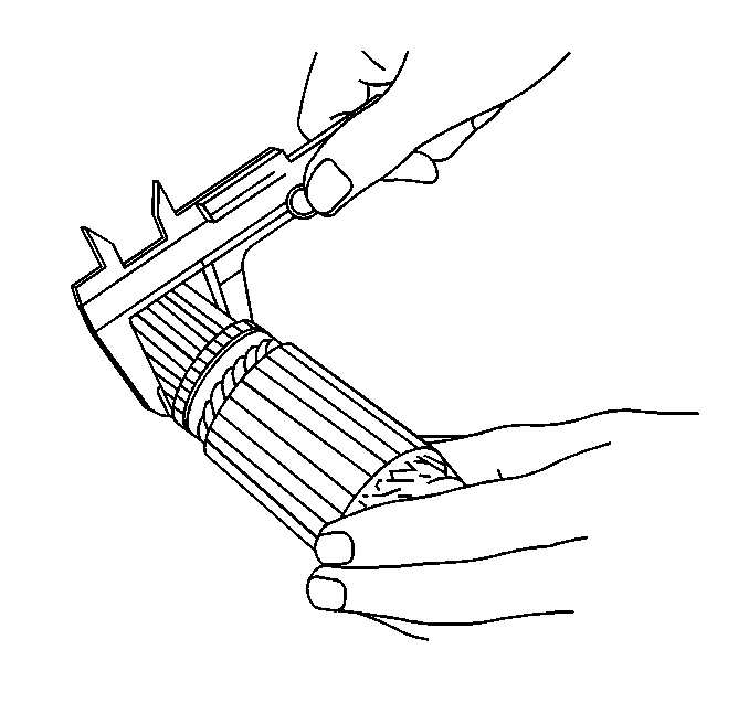
Commutator Outside Diameter
The standard is 36 mm (1.42 in) or less. The limit
is 35 mm (1.38 in).
Armature Coil
- Place the armature in a growler tester.
- Hold a hacksaw blade against the armature core. Slowly rotate the armature. If the armature is shorted, the hacksaw blade will vibrate. Replace the armature assembly if it is shorted.
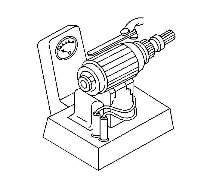
Armature Continuity
- Use a circuit tester to check for continuity between the commutator segments.
- If there is no continuity between any two points on the commutator, the armature assembly must be replaced.
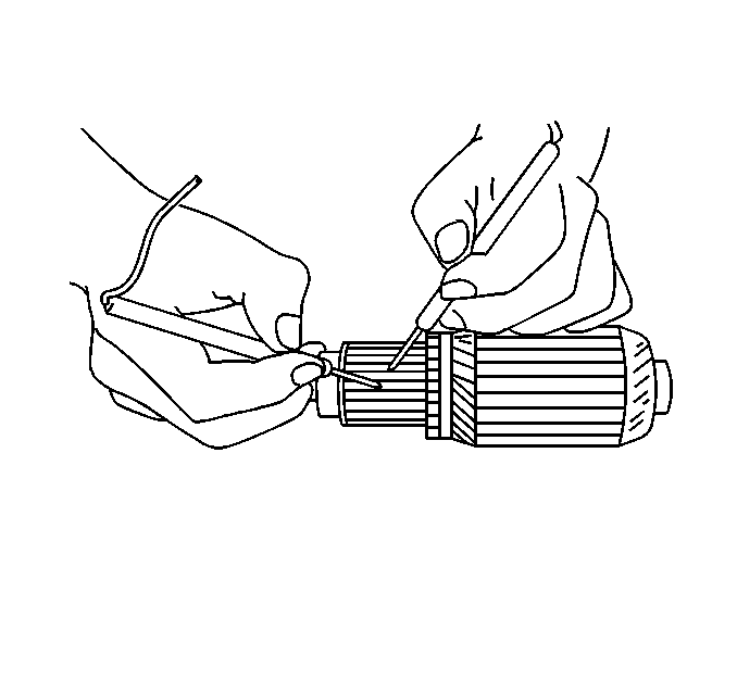
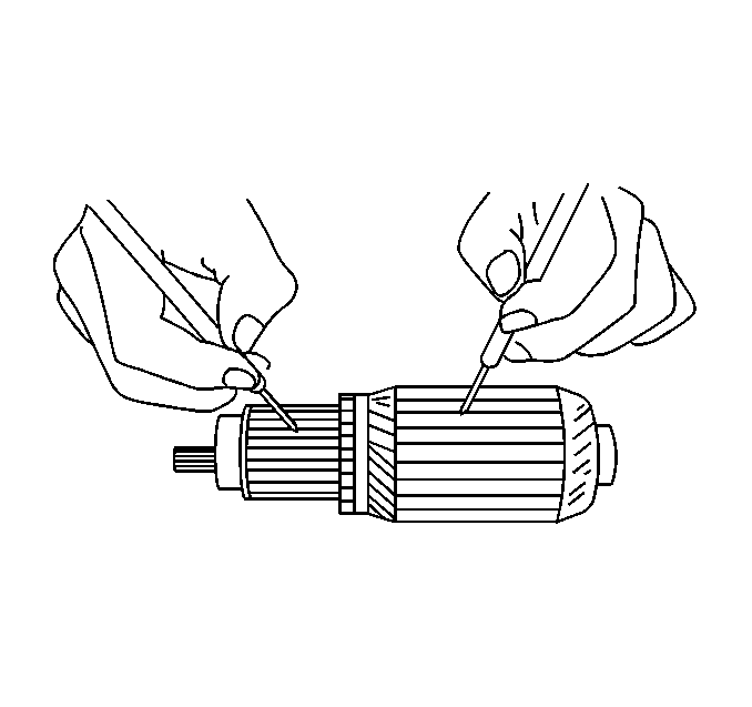
Armature Insulation
- Use a circuit tester to check that there is no continuity between the commutator segments and the coil core.
- If there is continuity between the commutator segments and the coil core, the armature assembly is defective and must be replaced.
Yoke
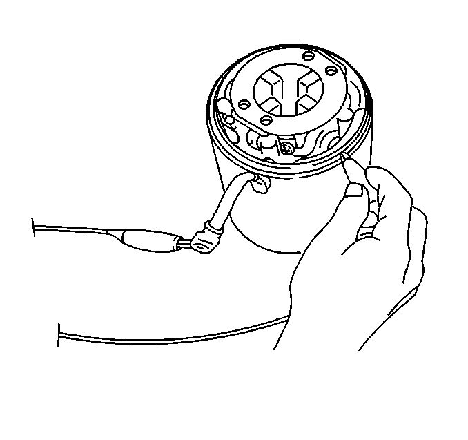
Field Coil Continuity
- Use a circuit tester to check for continuity between the connecting leads and the brushes.
- Replace the yoke assembly if there is no continuity at any point.
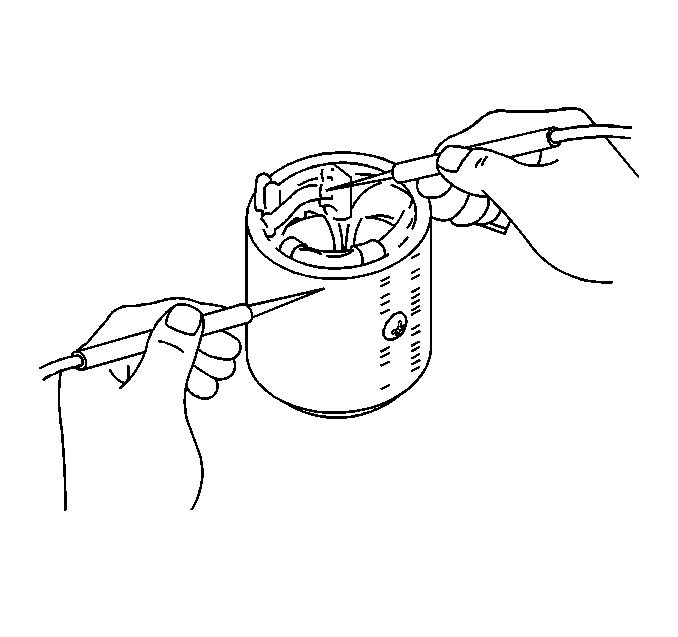
Yoke Insulation
- Use a circuit tester to check that there is no continuity between the field coil and the yoke body.
- If there is continuity between the field coil and the yoke body, the yoke assembly is defective and must be replaced.
Brush and Brush Holder
Brushes
- Use a vernier caliper to measure the brush lengths (four brushes).
- Replace the brushes as a set if one or more of the brush lengths is less than the specified limit.
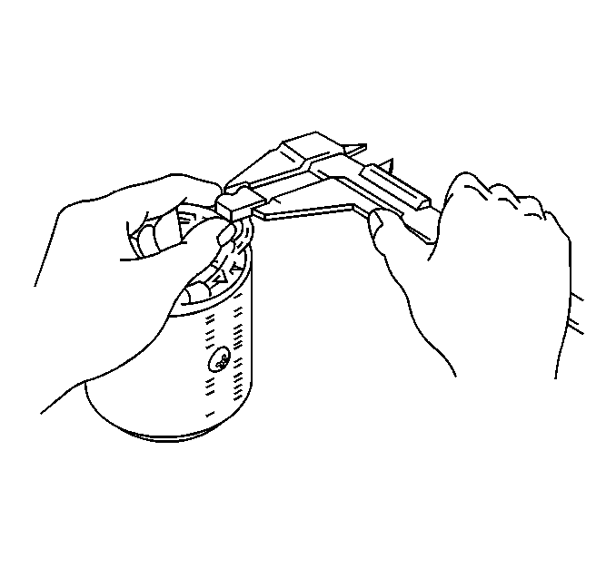
Brush Length
The specified length limit is 12 mm (0.47 in).
Brush Holder Insulation
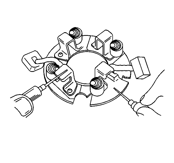
- Use a circuit tester to check that there is no continuity between the battery side brush cages and the holder plate.
- If there is continuity between the battery side brush cages and the holder plate, the brush holder assembly is defective and must be replaced.
Pinion Clutch
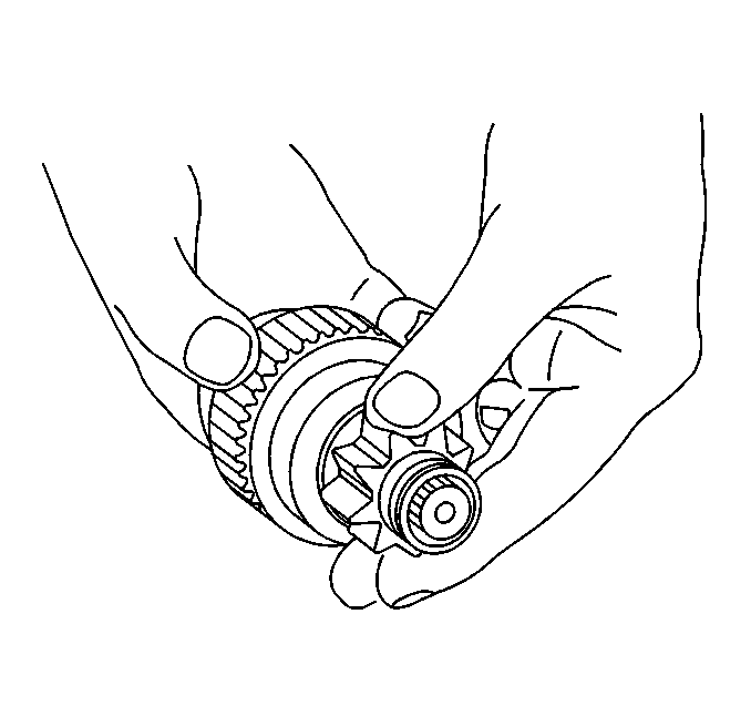
- Clean the pinion clutch with a clean rag.
- Check the pinion clutch and pinion gear for excessive wear and damage.
- Turn the pinion gear clockwise. The gear should turn smoothly with no resistance. If the gear does not turn smoothly, the pinion clutch assembly must be replaced.
- Turn the pinion gear counterclockwise. The gear should lock up firmly. If the gear does not lock firmly, the pinion clutch assembly must be replaced.
Bearing
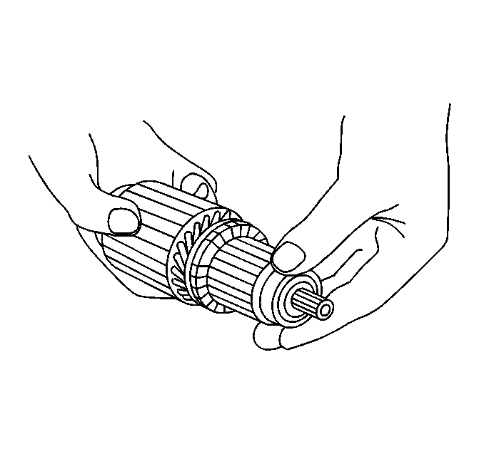
Inspect the bearings for excessive wear and damage. Replace the bearings if necessary.
Magnetic Switch
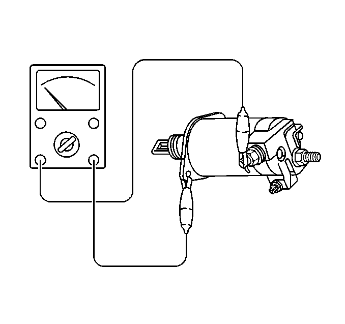
Inspect the continuity between the M terminal and the case of the magnetic switch using a circuit tester.
