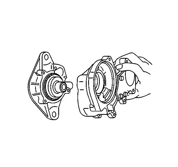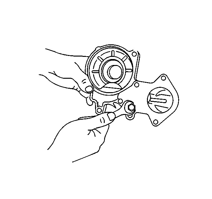
- Install the center bracket.
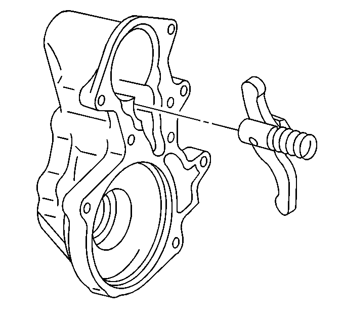
- Install the shift lever.
| 2.1. | Apply molybdenum disulfide grease to the shift lever pin. |
| 2.2. | When installing the shift lever, pay attention to its installing
direction as illustrated. |
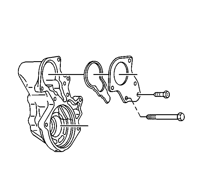
- Install the plate and gasket using the following
procedure:
| 3.1. | Install the plate and gasket to the center cover. |
Notice: Use the correct fastener in the correct location. Replacement fasteners
must be the correct part number for that application. Fasteners requiring
replacement or fasteners requiring the use of thread locking compound or sealant
are identified in the service procedure. Do not use paints, lubricants, or
corrosion inhibitors on fasteners or fastener joint surfaces unless specified.
These coatings affect fastener torque and joint clamping force and may damage
the fastener. Use the correct tightening sequence and specifications when
installing fasteners in order to avoid damage to parts and systems.
| 3.2. | Install the plate
bolts. |
Tighten
Tighten the bolts to 9 N·m (78 lb in).
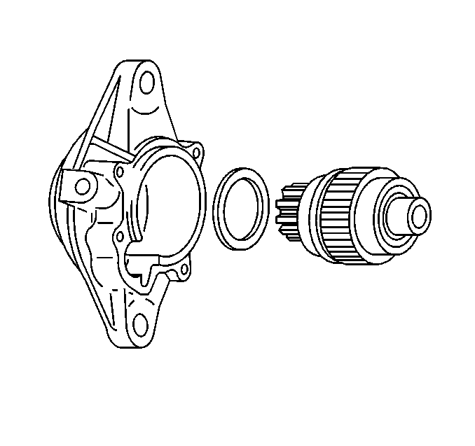
- Install the over running clutch.
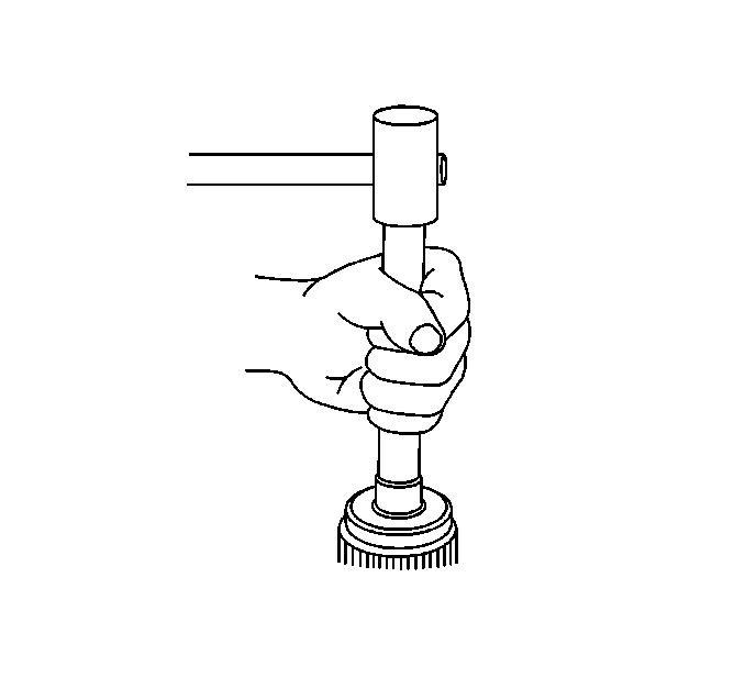
- Install the pinion.
- Install the pinion stopper.
- Install the return spring.
- Install the cup ring.
- Install the pinion stopper clip.
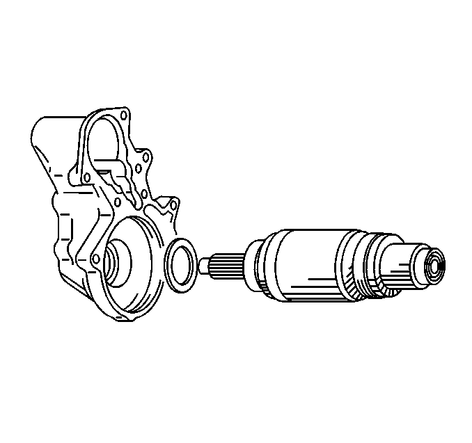
- Adjust the over running clutch front bracket
and bearing clearance with the adjusting washer so that the clearance may
become as specified.
Front Bracket and Bearing Clearance
The clearance should be 0.2-0.8 mm (0.008-0.031 in).
- Install the yoke assembly.
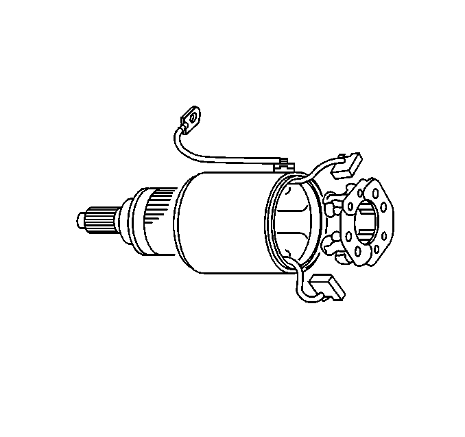
- Install the brush holder and spring.
- Adjust the armature center bracket and bearing clearance with
the adjusting washer so that the clearance may become as specified:
Center Bracket and Bearing Clearance
The clearance should be 0.2-0.8 mm (0.008-0.031 in).
- Install the brushes.
- Install the rear bracket.
- Install the brush holder screw.
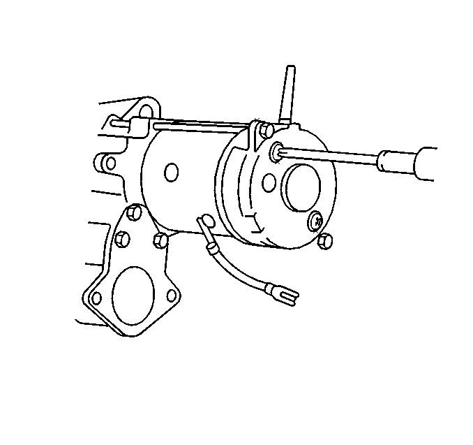
- Install the through bolt.
Tighten
Tighten the bolt to 9 N·m (78 lb in).
- Install the magnetic switch assembly using the following procedure:
| 18.1. | Install the magnetic switch assembly to the center bracket. |
| 18.2. | Install the magnetic switch assembly bolts. |
Tighten
Tighten the bolt to 9 N·m (78 lb in).
- Connect the lead wire.
