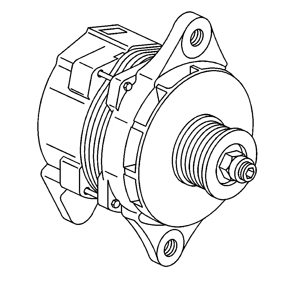
The charging system consists of the following components:
| • | The voltmeter and charging system indicator lamp circitry |
The generator supplies electrical power in order to charge the battery
and operate the accessories. This vehicle uses the 21-SI 200 generator.
These generators are of the SI (Systems Integral) series. SI generators
have a built-in regulator.

The solid state regulator and the brush holder assembly attach to the
slip ring end frame. The regulator voltage setting is not adjustable.
The regulator is equipped with the following terminals:
| • | The R (Relay) terminal. |
| | The R terminal operates auxiliary equipment in some circuits, such as
the tachometer. |
| • | The I (Indicator) terminal. |
| | The I terminal feeds an indicator lamp or a gauge. |
The rotor bearings contain enough grease in order to eliminate the need
for periodic lubrication. Two brushes carry current through the two slip rings
to the field coil. The field coil mounts on the rotor. Under normal operating
conditions, the field coil provides long periods of attention-free service.
The stator windings are assembled on the inside of a laminated core
that forms part of the generator frame. A rectifier bridge that connects to
the stator windings contains six diodes. The rectifier bridge
electrically changes the stator AC voltages to DC voltage. This DC voltage
appears at the generator output BAT terminal. A diode trio that connects
to the stator windings supplies the generator field current. A capacitor
or a condenser mounted to the end frame protects the rectifier bridge and
diode trio from high voltages. The capacitor or the condenser also suppresses
radio noise.

