The angle of the steering arms determines the turning angle or toe-out on turns.
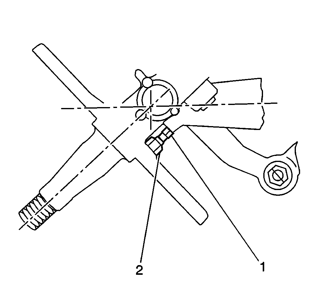
Ensure that the stop screw adjustment provides 16 mm (0.6250 in) minimum clearance of the tire with all chassis components installed, regardless of the maximum turning angles. The stop screws are installed in the steering knuckles and stop against the axle center.
- Remove the wheel speed sensor if equipped.
- Hold the right wheel tightly against the right turn position, with the wheels turned to the extreme right.
- Turn out the stop screw until the stop screw contacts firmly against the stop.
- Turn the stop screw one more turn against the stop.
- Verify the position of the tire. Adjust the tire as necessary in order to provide 16 mm (0.6250 in) clearance to all chassis components.
- Tighten the jam nut on the stop screw.
- Repeat the previous six steps for the left side stop screw adjustment, turning the wheel to the left in step 2.
- Recheck the turning clearance and the stop screw setting when installing oversize tires.
- Verify the position of the tire. Adjust the tire as necessary in order to provide 16 mm (0.6250 in) clearance to all of the chassis components.
- Install the wheel speed sensor if equipped.

Loosen the jam nut (2) and the right stop screw (1) in order to prevent the stop screw from contacting its stop when the wheels are turned to the extreme right.
Notice: Use the correct fastener in the correct location. Replacement fasteners must be the correct part number for that application. Fasteners requiring replacement or fasteners requiring the use of thread locking compound or sealant are identified in the service procedure. Do not use paints, lubricants, or corrosion inhibitors on fasteners or fastener joint surfaces unless specified. These coatings affect fastener torque and joint clamping force and may damage the fastener. Use the correct tightening sequence and specifications when installing fasteners in order to avoid damage to parts and systems.
Tighten
Tighten the jam nut to 65 N·m (48 lb ft).
