Removal Procedure
Tools Required
- Set the parking brake.
- Block the vehicle rear wheels.
- Raise the front of the vehicle until the tires clear the floor.
Notice: Do not use the front crossmember to support the vehicle or the crossmember
may buckle.
- Support the frame using suitable safety stands.
- Remove the wheels, the hubs, and the bearings.
- Refer to
Front Wheel Hub, Bearing, and Seal Replacement
.
- Remove the brake components as needed.
- Refer to
Brake Caliper Replacement
.
- Remove the brake backing plates and the dust covers.

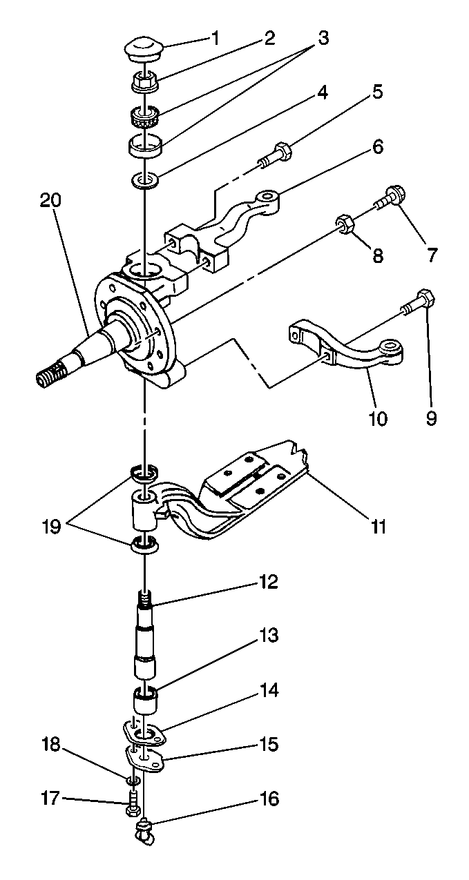
- Remove the tie rod arm bolts (9). Lower the tie rod arm (10) and the
tie rod to the floor.
- Remove the steering arm bolts (5). Support the steering arm (6)
and the steering rod out of the way.
- Remove the king pin upper cap (1).
- Remove the following components:
| • | The king pin lower cap (15) |
- Remove the king pin nut (2).

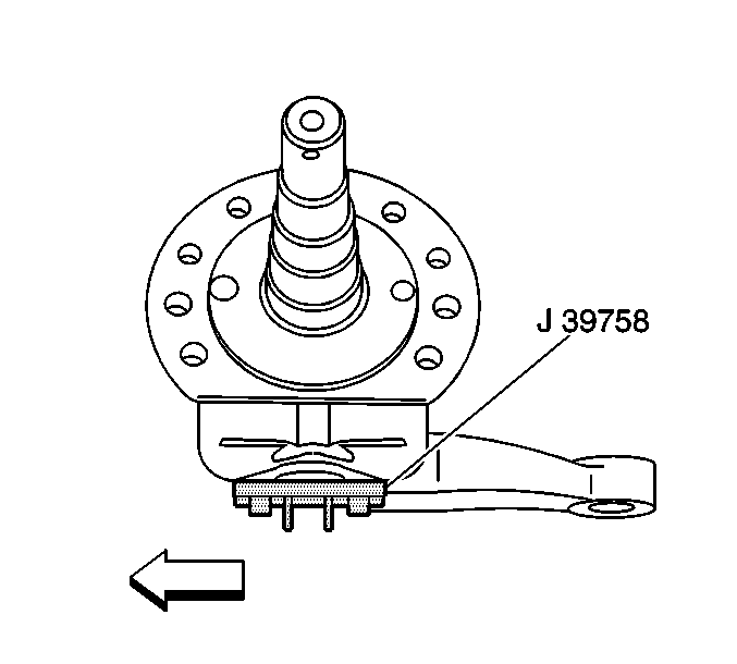
- Using the J 39758
, insert the tool pins into the holes
at the bottom of the king pin.
- Align the tool's bolt holes.
- Secure with two bolts into the steering knuckle in order to prevent
the king pin from spinning.

- Remove the king pin (12) by knocking out the pin with a soft-faced mallet.
- Remove the steering knuckle (20).
- Support the knuckle in a vise.
- Remove the following components from the knuckle (20):
- Remove the king pin bushing (13), if required. Refer to
King Pin Bushing and Bearing Cup Replacement
.
Inspection Procedure

- Clean the axle components using a cleaning solvent.
- Soak the thrust bearing until all of the old lubricant is gone.
- Inspect the axle components for the following conditions:
- Use Magna-Flux™ inspection, if available, in order to inspect
the steering knuckles (20) and the kingpins (12) for minute cracks, checks,
or fractures.
- Inspect the king pin bearings and the cups for rough rotation.
- Inspect the bores in the axle king pin (12) for the following
conditions:
- Inspect the bores in the king pin bushing (13) for the following:
- Smooth the bore using a crocus cloth or a fine grit sandpaper
if needed. Clean the bore.
Installation Procedure

- Install the king pin bushings (13), if removed.
- Install the king pin bearing cup, if removed.
- Install the steering knuckle (20).
- Install the king pin (12) and install the dust seals (19).
- Install a shim or spacer (4).
- Install the king pin thrust bearing (3). Pack the bearing thoroughly
with high temperature wheel bearing grease.
- Install the king pin nut (2).

- Using the J 39758
insert the tool pins into the holes
at the bottom of the king pin.
- Align the tool's bolt holes.
Notice: Use the correct fastener in the correct location. Replacement fasteners
must be the correct part number for that application. Fasteners requiring
replacement or fasteners requiring the use of thread locking compound or sealant
are identified in the service procedure. Do not use paints, lubricants, or
corrosion inhibitors on fasteners or fastener joint surfaces unless specified.
These coatings affect fastener torque and joint clamping force and may damage
the fastener. Use the correct tightening sequence and specifications when
installing fasteners in order to avoid damage to parts and systems.
- Secure the tool
with two bolts into the steering knuckle in order to keep the king pin from
spinning.
Tighten
Tighten the king pin nut (2) to 550 N·m (406 lb ft).

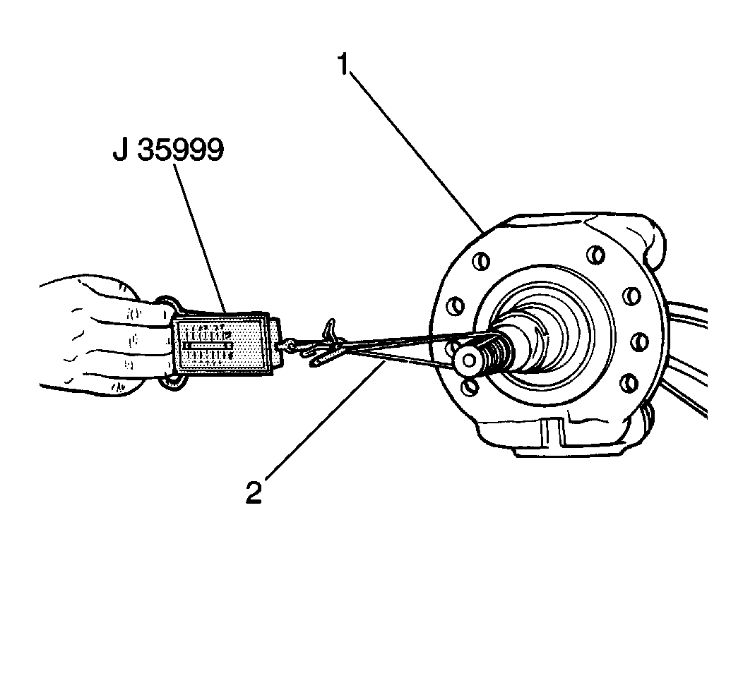
- Measure the king pin bearing
preload. Refer to
King Pin Bearing Preload
.

- Install the following components:
Tighten
Tighten the dust cap bolt to 24 N·m (18 lb ft).
- Install the king pin upper dust cap (1). Tap the dust cap into
place using a soft-faced mallet. Grease the knuckle (20) through the lubrication
fitting (16) on the bottom.
- Install the tie rod arm (10).
- Install the steering arm (6), if removed.
- Install the brake backing plate and the dust cover.
- Install the brake components as needed.
- Refer to
Brake Caliper Replacement
.
- Install the wheel bearings, the hubs, and the wheels.
- Refer to
Front Wheel Hub, Bearing, and Seal Replacement
- Remove the safety stands and lower the vehicle.
- Check the axle alignment.
- Check the stop screw (7,8) adjustment. Adjust as needed. Refer
to
Stop Screw Adjustment
in Wheel Alignment.


