The electric shift control system includes the following components:
| • | A control switch |
| • | A speedometer adapter assembly |
| • | A shift motor assembly |
| • | A relay |
| • | A wiring harness |
Control Switch

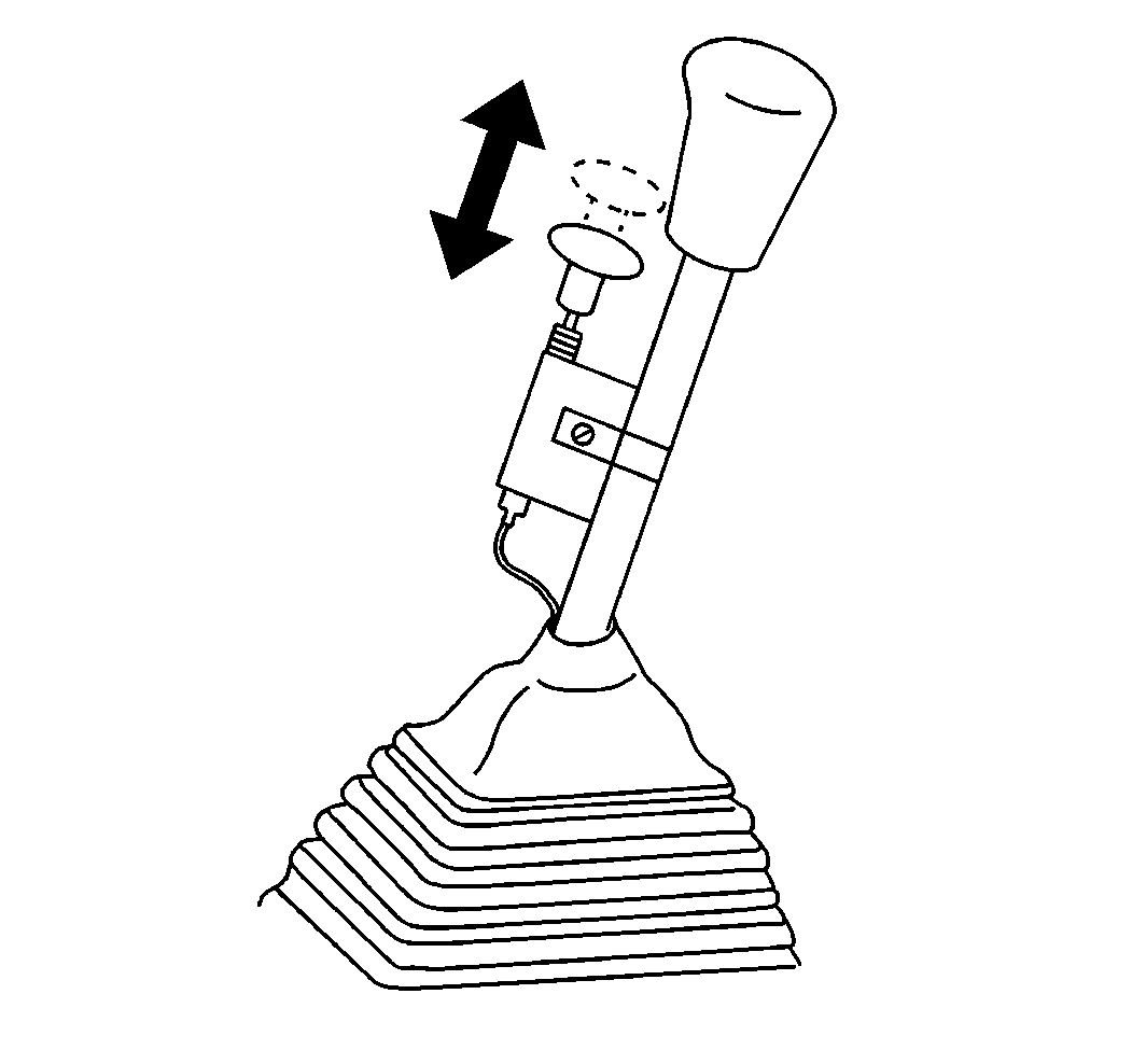
In manual transmission models, the two speed rear axle control switch is mounted on the manual transmission shift lever.
The control switch consists of a shift button that is positioned by the driver in order to operate the two speed shift motor assembly at the rear axle.
The driver selects the axle speed by moving the shift mounted control switch down or up in order to select the LOW or HIGH axle range.

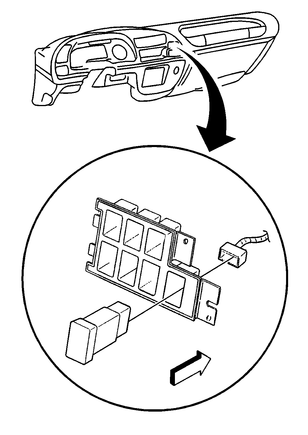
In automatic transmission models, the two speed rear axle control switch is mounted in the instrument panel.
The driver selects the axle speed by pushing the switch for the LOW or HIGH axle range.
Relay
The relay is mounted to the crossmember in front of the rear axle.
When the control switch is in the HIGH position a ground is supplied to the relay. This condition actuates the shift motor to the HIGH speed range.
When the control switch is returned to the LOW position the relay is de-energized. This condition returns the shift motor to the LOW speed range.
Shift Motor Assembly
The shift motor assembly is mounted on the differential carrier.
The shift motor shifts the axle into the LOW or HIGH speed range.
Speedometer Adapter Assembly
A speedometer adapter assembly matches the ratio of the speedometer to the ratio of the rear axle.
The adapter gives an accurate speedometer reading when the axle is shifted from one ratio to the other.
The speedometer adapter assembly is electrically connected to the rear axle control switch.
When the shift control switch is placed in the LOW position, an electric signal changes the speedometer adapter assembly to the LOW ratio in order to match the rear axle.
When the shift control switch is placed in the HIGH position, the electric signal is removed and the speedometer adapter assembly reads the HIGH ratio of the rear axle.
