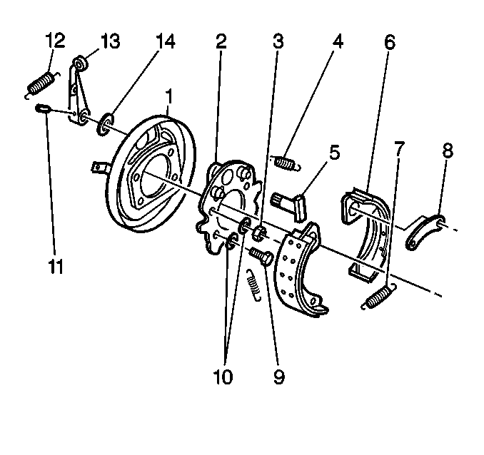
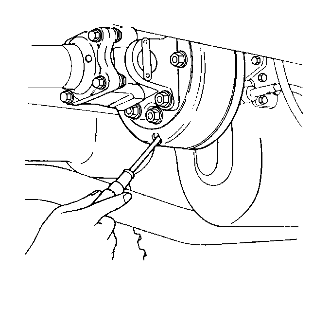
Brake Drum Replacement Bendix 254 mm - 10 in
Removal Procedure
- Block the wheels .
- Release the parking brake.
- Remove the propeller shaft. Refer to the appropriate replacement procedure in Propeller Shaft:
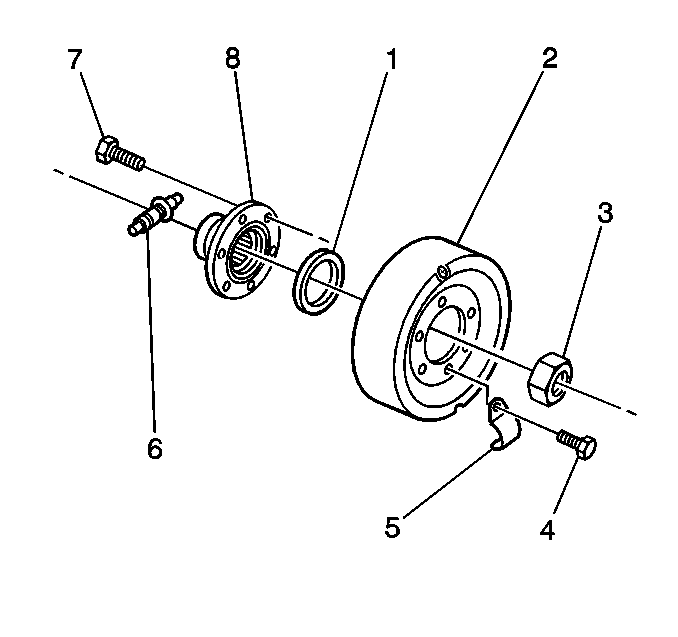
- Remove the bolts (9).
- Remove the washers (10).
- Remove the covers (5).
- Remove the drum (2).
- Measure the drum diameter.
- Replace the drum if the ID is more than 256 mm (10.08 in).
- Measure the drum run-out.
- Replace the drum if the run-out varies by more than 0.05 mm (0.002 in).


Installation Procedure
- Install the drum (2).
- Install the covers (5).
- Install the bolts (9).
- Install the washers (10).
- Align the drum holes with the flange holes.
- Install the propeller shaft. Refer to the appropriate replacement procedure in Propeller Shaft:
- Adjust the brake linings.
- Verify the operation of the parking brake.
- Remove the wheel blocks.


Brake Drum Replacement Bendix 229 mm - 9 in
Removal Procedure
- Block the wheels.
- Remove the propeller shaft. Refer to the appropriate replacement procedure in Propeller Shaft:
- Remove the following items from the center of the yoke:
- Straighten the lock tab on the washer.
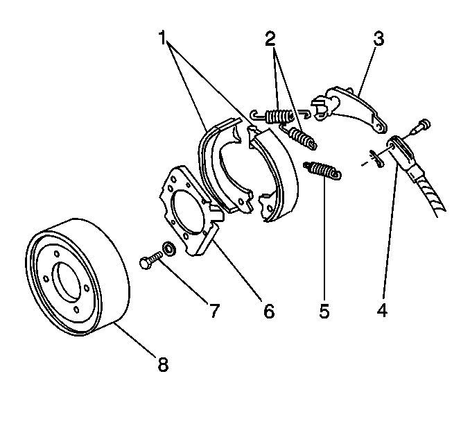
- Remove the brake drum (8) and the yoke assembly from the transmission.
- Remove the bolts that hold the drum (8) to the yoke.
- Inspect the drum (8) for the following:
- Repair the drum as needed.
- Inspect the linings (1) for contamination and excessive wear. The minimum lining thickness (with bonded linings) is 1.52 mm (0.060 in).
- If replacement is necessary, replace the linings as a set.
- Inspect the brake mechanism for proper operation.
- Repair the brake mechanism as needed.

| • | The companion flange bolt |
| • | The washer |
| • | The retainer |
Important: Closely examine all mounting bolt holes in the drum for stress cracks.
| • | Cracks |
| • | Scoring |
| • | Pitting |
| • | Grooves |
| • | Overheating damage |
Installation Procedure
- Install the bolts that hold the drum (8) to the yoke.
- Install the drum and yoke assembly to the transmission.
- Install the companion flange bolt and a new washer to the transmission mainshaft at the center of the yoke.
- Install the propeller shaft. Refer to the appropriate replacement procedure in Propeller Shaft:
- Adjust the parking brake. Refer to Parking Brake Shoe Replacement .
- Remove the wheel blocks.

Notice: Use the correct fastener in the correct location. Replacement fasteners must be the correct part number for that application. Fasteners requiring replacement or fasteners requiring the use of thread locking compound or sealant are identified in the service procedure. Do not use paints, lubricants, or corrosion inhibitors on fasteners or fastener joint surfaces unless specified. These coatings affect fastener torque and joint clamping force and may damage the fastener. Use the correct tightening sequence and specifications when installing fasteners in order to avoid damage to parts and systems.
Tighten
Tighten the companion flange bolt to 140 N·m (103 lb ft).
