Air Drum Brake Adjustment Pushrod Stroke Measurement
Refer to
Maintenance Schedule
in Maintenance and Lubrication.
Measure the pushrod stroke in order to determine if the brakes are acceptably
adjusted. The pushrod travel should be less than the maximum allowable stroke
listed in the Dimensional Specifications Table. Refer to
Air Drum Brake Component Specifications
.
Pushrod Stroke Measurement
The stroke is the difference between the released air brake automatic
slack adjuster position and the applied air brake automatic slack adjuster
position. The applied position must be measured at 550-620 kPa
(80-90 psi) air pressure in the brake chamber assemblies
when the brakes are fully applied.
- Start the engine to increase the air pressure to 690 kPa
(100 psi) if necessary.
- Stop the engine.
- Apply and release the brakes to decrease the air pressure to 690 kPa
(100 psi) if necessary.

- Check the duel air pressure
gauge in order to ensure that the air pressure in the air reservoirs is 690 kPa
(100 psi) with the engine off and that the rear air brake chambers
(spring brake chamber section) is released.
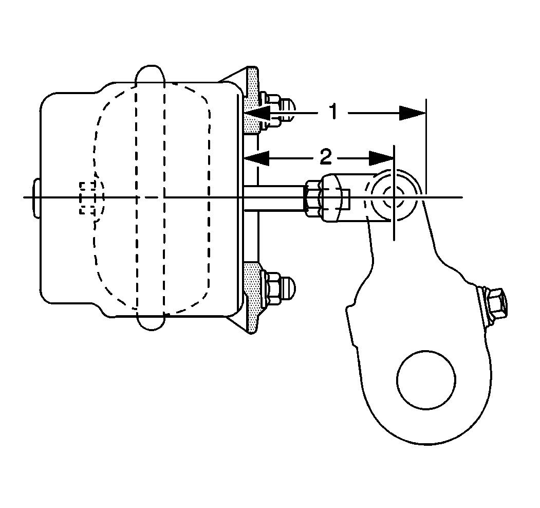
- Measure the distance between the brake chamber assembly mounting
surface and the center of the air brake chamber clevis pin on all of the brakes.

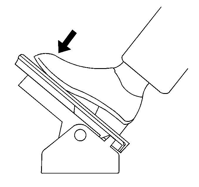
- Have an assistant apply
and hold one full brake application.
- Measure the distance between the brake chamber assembly mounting
surface and the center of the air brake chamber clevis pin on all of the brakes
with the brakes applied at 550-620 kPa (80-90 psi).
- Release the brakes.
- Calculate the adjusted air brake chamber stroke at each brake.
| 9.1. | Subtract the dimension in measurement number 1 from the dimension
in measurement number 2. |
| 9.2. | The difference between the two dimensions is the adjusted air
brake chamber stroke. The adjusted air brake chamber stroke must not be greater
than the stroke length shown in the Dimensional Specifications Table. Refer
to
Air Drum Brake Component Specifications
. |
Air Drum Brake Adjustment Normal Wear Adjustment
Air Brake Automatic Slack Adjuster (Rockwell)

- Block the wheels.
- Cage the rear air brake chambers. Refer to
Caging the Rear Air Brake Chamber
.
- Raise the vehicle and support the vehicle with safety stands.
Refer to
Lifting and Jacking the Vehicle
in General Information.
- Adjust the brakes.
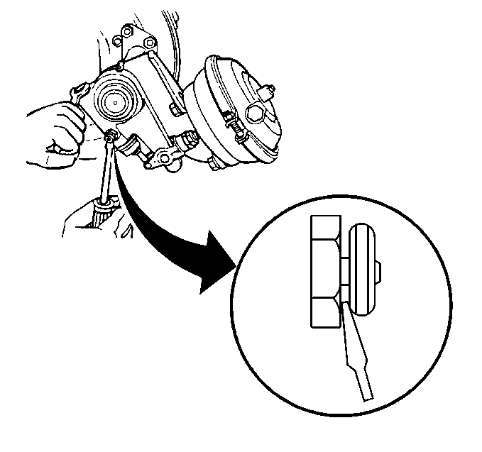
| 4.1. | Disengage the pawl assembly with a screwdriver. |
| 4.2. | Turn the slack adjuster adjusting nut until the brake linings
contact the brake drum. |
| 4.3. | Rotate the slack adjuster adjusting nut 180 degrees (1/2 turn). |
- Release the pawl.
- Measure the air brake chamber pushrod stroke. Refer to
Air Drum Brake Adjustment
.
- Repeat step 4 and step 5 on each wheel until all of the brakes
have been adjusted.
- Lower the vehicle.
- Uncage the rear air brake chambers. Refer to
Caging the Rear Air Brake Chamber
.
- Check for proper brake operation.
- Set the parking brake.
- Remove the wheel blocks.
Air Brake Automatic Slack Adjuster (Eaton®)
- Block the wheels.
- Cage the rear air brake chambers. Refer to
Caging the Rear Air Brake Chamber
.
- Raise the vehicle and support the vehicle with safety stands.
Refer to
Lifting and Jacking the Vehicle
in General Information.
- Turn the slack adjuster adjusting hex clockwise until the brake
linings contact the brake drum.
- Rotate the slack adjuster adjusting hex counterclockwise 180 degrees
(1/2 turn).
A minimum of 17.62 N·m (13 lb ft) is necessary
in order to overcome the clutch. You will hear a racheting sound.
- Measure the air brake chamber pushrod stroke. Refer to
Air Drum Brake Adjustment
.
- Repeat steps 4-6 on each wheel until all of the brakes have
been adjusted.
- Lower the vehicle.
- Uncage the rear air brake chambers. Refer to
Caging the Rear Air Brake Chamber
.
- Check for proper brake operation.
- Set the parking brake.
- Remove the wheel blocks.


