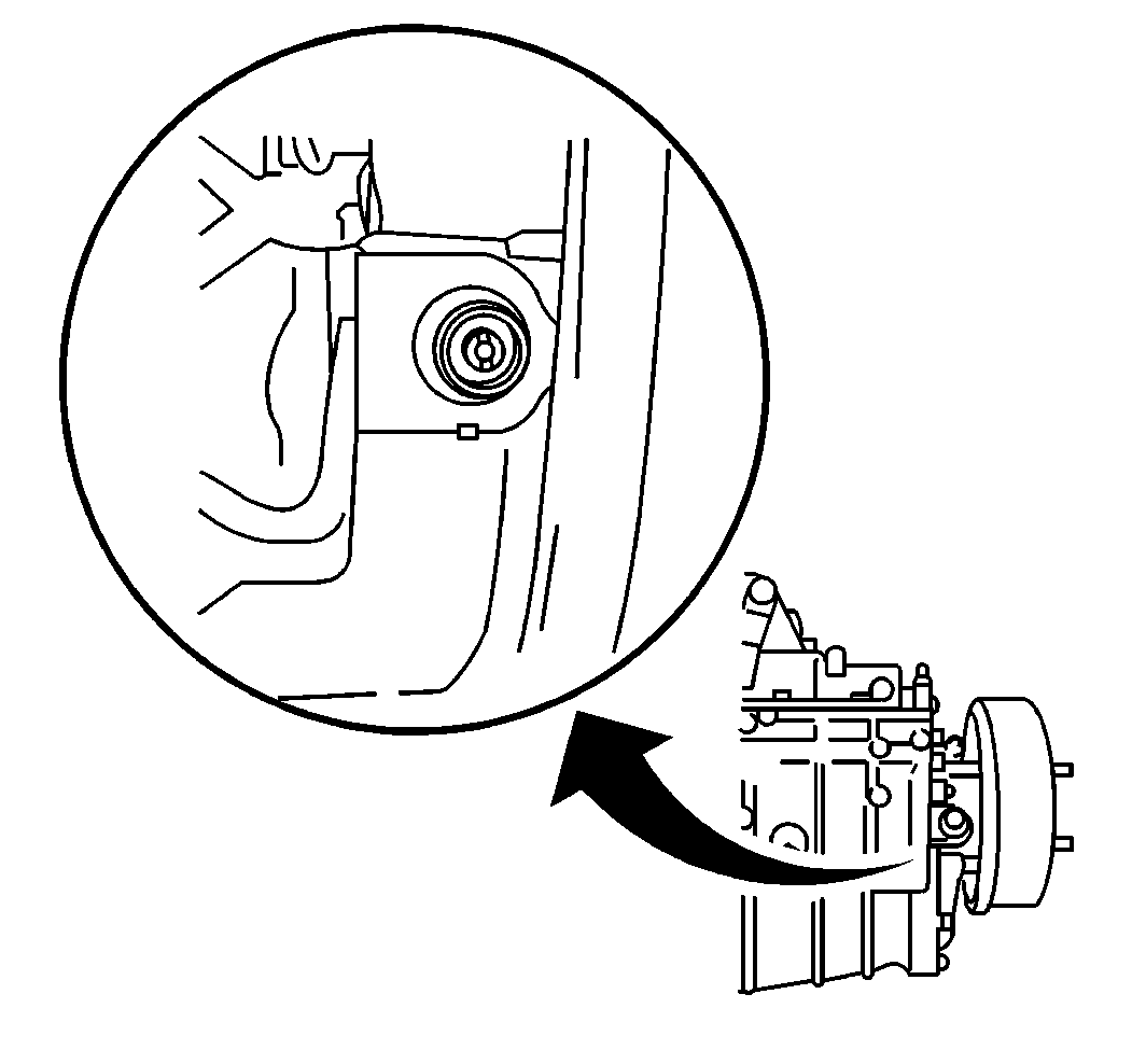
- Remove the speedometer driven gear from the transmission. Refer to Speedometer Driven Gear Replacement .
- Position the speedometer driven gear and the speedometer driven gear bushing into the transmission case rear cover.
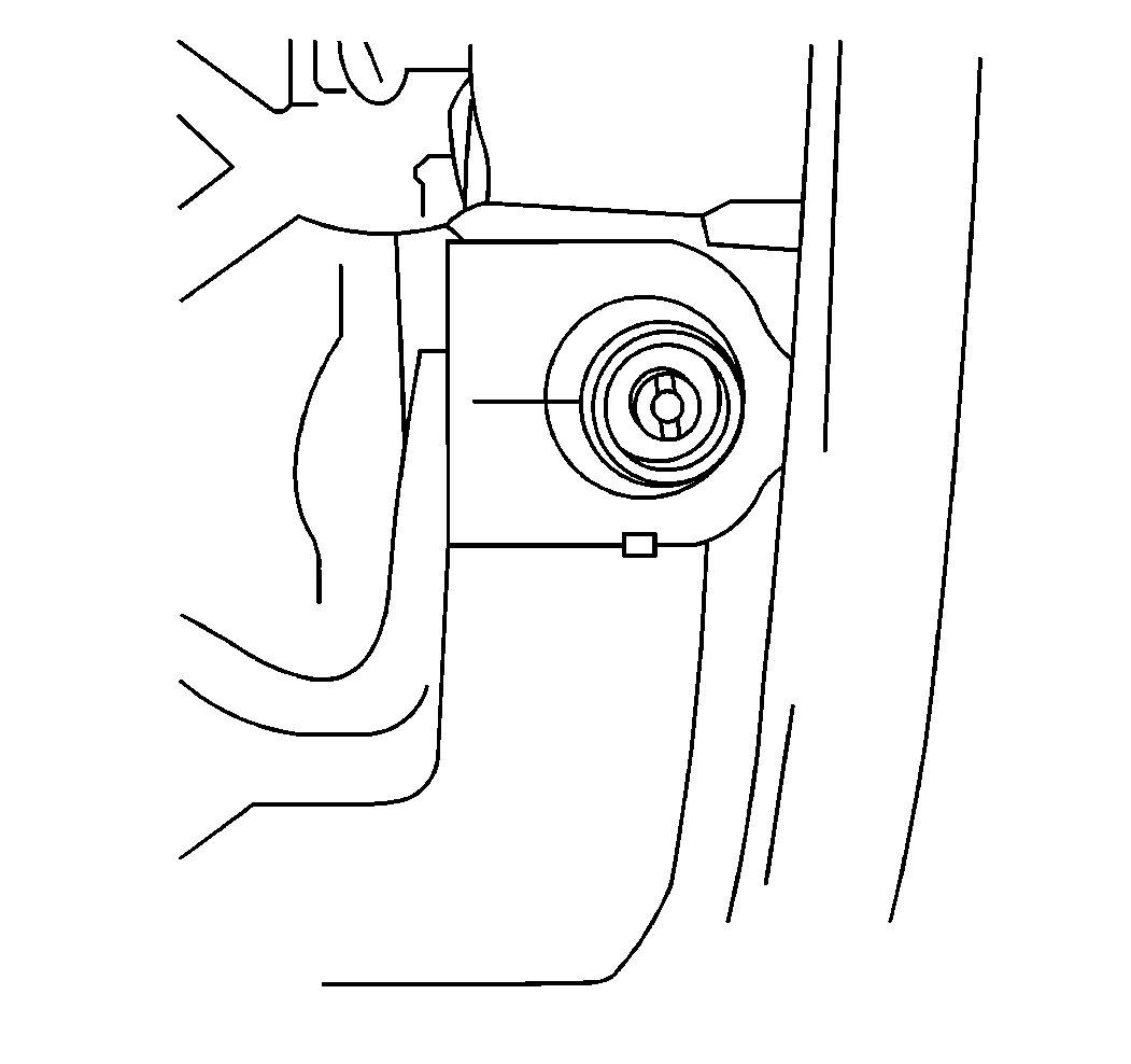
- Rotate the bushing in the direction toward the front of the vehicle until there is no backlash between the speedometer driven gear and the transmission drive gear.
- Mark the bushing and transmission case rear cover.
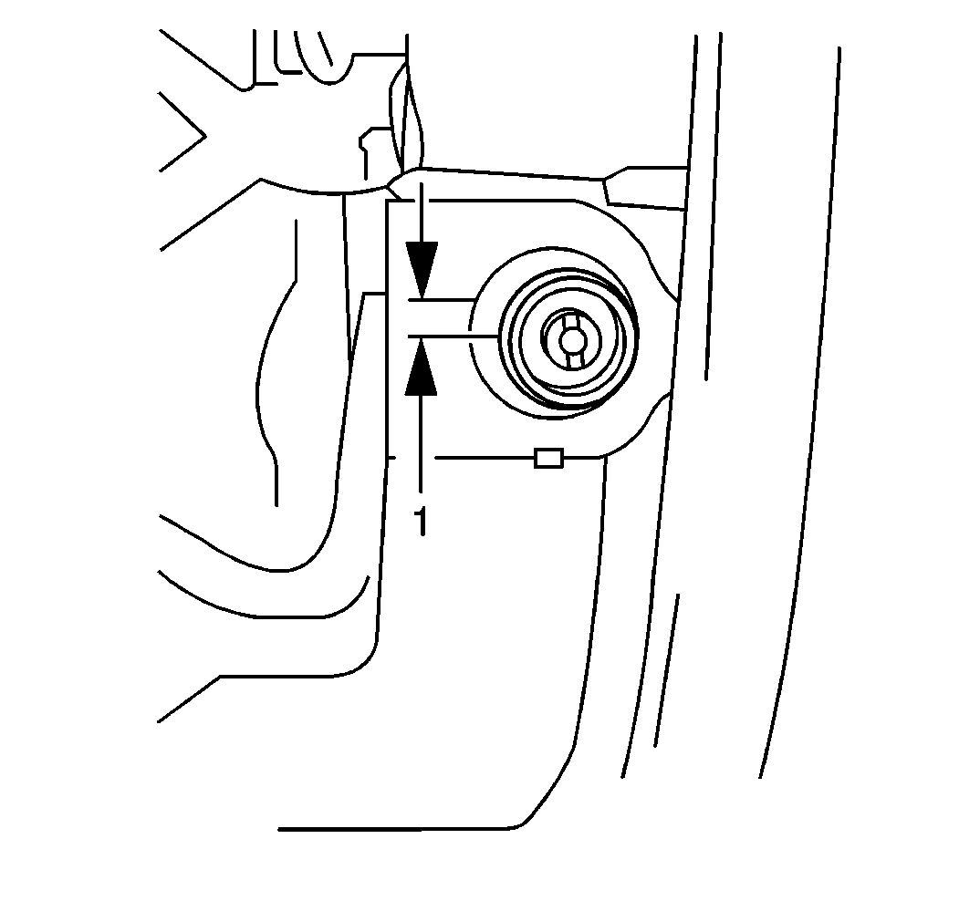
- Rotate the bushing in the reverse direction (1) by the measurement shown in the Reverse Direction Distance Table.
- Using a marker pin, mark a set screw hole boring position on the bushing through the rear case set screw mounting hole.
- Remove the bushing and speedometer driven gear from the transmission rear case.
- Drill a set screw access hole into the bushing.
- Install the following components into the transmission rear case:
- Align the access hole in the bushing with the set screw hole.
- Install the set screw and washer.
- Install a new speed sensor seal and seal sensor.


Notice: The backlash between the gears will be in the specified range 0.1-0.3 mm (0.138-0.157 in) after performing this procedure.
Drill one 4.5 mm (0.177 in) hole 3.5--4.0 mm (0.138-0.157 in) depth into the bushing.
| • | The speedometer driven gear |
| • | The speedometer driven gear seal |
| • | The speedometer driven gear bushing |
Notice: Use the correct fastener in the correct location. Replacement fasteners must be the correct part number for that application. Fasteners requiring replacement or fasteners requiring the use of thread locking compound or sealant are identified in the service procedure. Do not use paints, lubricants, or corrosion inhibitors on fasteners or fastener joint surfaces unless specified. These coatings affect fastener torque and joint clamping force and may damage the fastener. Use the correct tightening sequence and specifications when installing fasteners in order to avoid damage to parts and systems.
Tighten
Tighten the set screw to 6 N·m (53 lb in).
