For 1990-2009 cars only
Removal Procedure
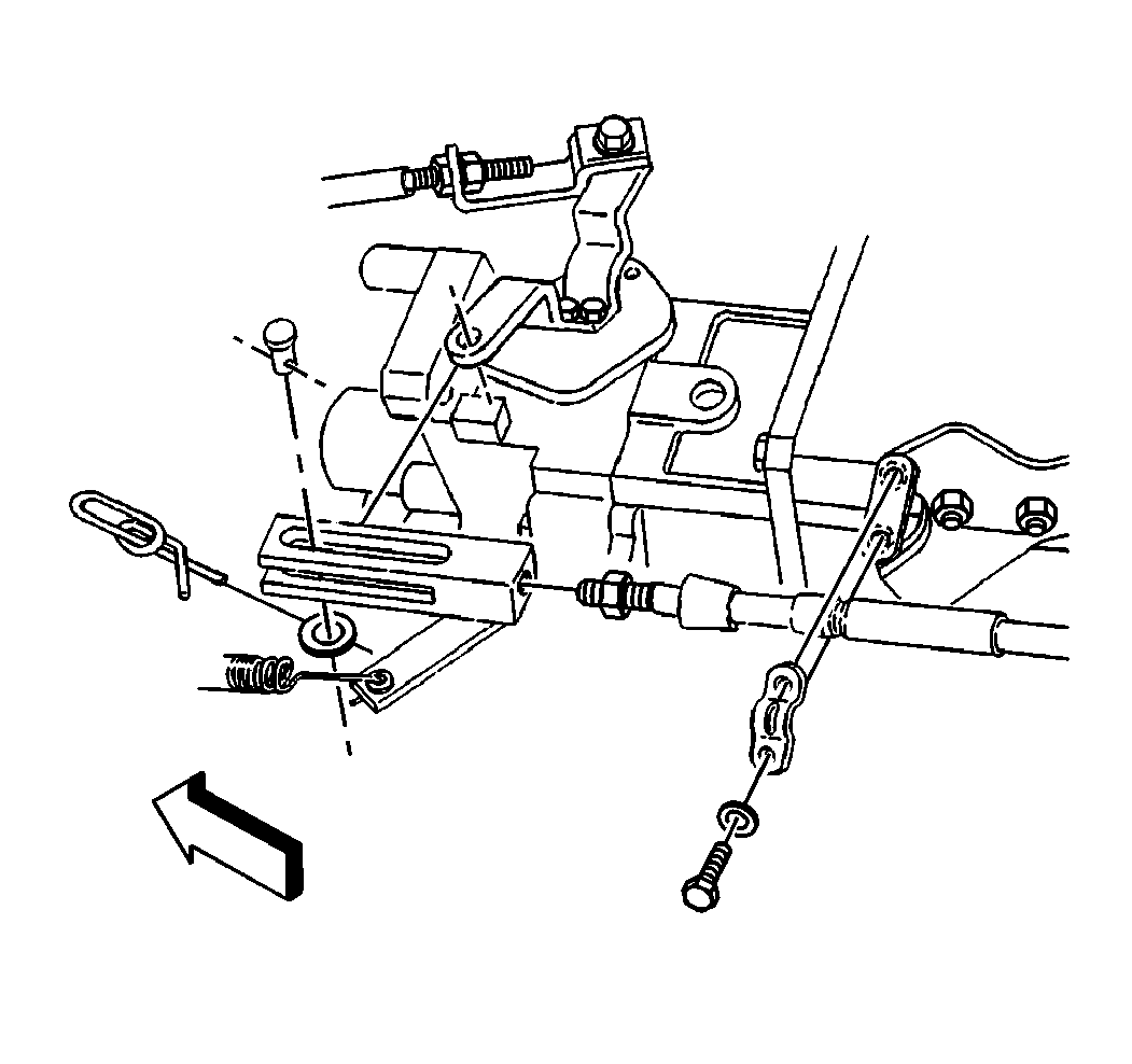
- Remove the cotter pin, the clevis pin, and the washer securing the clevis to the throttle lever, if necessary.
- Remove the clevis from the modulator cable, if necessary.

Adjustment Procedure
- Install the clevis to the modulator cable.
- Install the threads of the modulator cable into the clevis to a 20 mm (0.8 in) thread engagement.
- With the engine OFF, position the throttle lever to the wide open position.
- Position the clevis over the throttle lever mounting hole.
- Position the clevis pin through the clevis and the throttle lever.
- Secure the modulator cable nut to the clevis.
- Secure the clevis pin to the clevis with the washer and the cotter pin.
- Move the throttle lever from the wide open throttle position to the idle position three or four times.
- Position the throttle lever in the wide open position.
- Make sure that the clearance between the clevis pin and the end of the clevis slot away from the cable is between 1-2 mm (0.04-0.08 in).
- Repeat the procedure, if necessary, in order to acquire the correct clearance.

| 5.1. | Make sure the distance between the clevis pin and the end of the clevis slot away from the cable is between 1-2 mm (0.04-0.08 in). |
| 5.2. | If the clearance is not between 1-2 mm (0.04-0.08 in), thread the modulator cable into or out of the clevis in order to acquire the correct clearance. |
Notice: Use the correct fastener in the correct location. Replacement fasteners must be the correct part number for that application. Fasteners requiring replacement or fasteners requiring the use of thread locking compound or sealant are identified in the service procedure. Do not use paints, lubricants, or corrosion inhibitors on fasteners or fastener joint surfaces unless specified. These coatings affect fastener torque and joint clamping force and may damage the fastener. Use the correct tightening sequence and specifications when installing fasteners in order to avoid damage to parts and systems.
Tighten
Tighten the modulator cable nut to 12 N·m (106 lb in).
