Power Steering Pump Disassemble LG4 with JE3
Disassemble Procedure
- Clean the exterior of the power steering pump with a suitable
cleaning solvent that will not damage the rubber components.

- Remove the following components
from the shaft (18):
| • | The gear (21) (the gear is a slip fit) |
- Remove the pump body bolts (1).
- Remove the following components from the front cover (12):

Important: The side plate, the ring, and the pressure plate must be assembled in
the exact position that they were removed.
- Mark the following components:

- Remove the following components
from the ring (6):
| • | The pressure plate screws (3) |
- Remove the following components from the ring (6):
- Remove the snap ring (20) from the front cover (12).
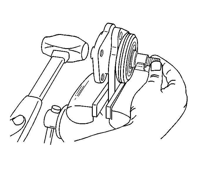
Important: Gently tap with a plastic mallet on the end opposite the drive end in
order to remove the shaft from the front cover.
- Remove the shaft from the front cover.

- Remove the retainer ring
(16) from the shaft (18).
- Remove the shaft seal (14) from the front cover (12).
- Remove the O-ring (13) from the front cover (12).
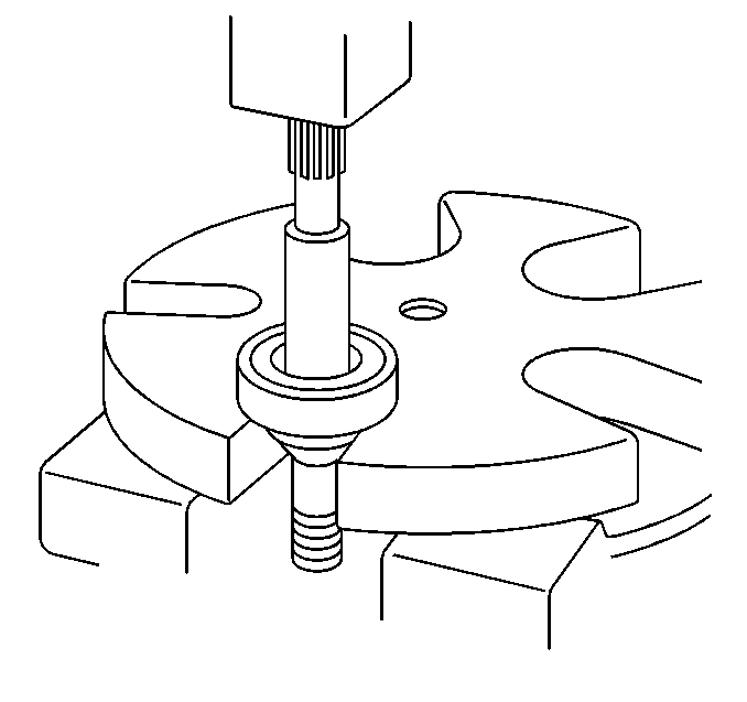
- Inspect the shaft bearing
Refer to
Wheel Bearings Diagnosis
in
Suspension General Diagnosis.
- If the shaft bearing needs to be replaced, perform the following
steps:
| • | Remove the snap ring from the shaft |
| • | Press the shaft bearing off of the shaft |
| • | Discard the shaft bearing |
Inspection Procedure

- Inspect the bushing for
the following conditions:
- If the bushing shows any of these conditions, the pump body (2)
must be replaced.
- Use a suitable solvent in order to clean all of the parts.
Dry all of the parts.
- Inspect the vane tips (7) for the following conditions:
- Inspect the inner surface of the ring (6) for the following conditions:
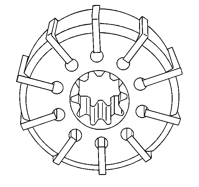
Important: The vanes must fit properly in the rotor slots, without sticking or
excessive play.
- Inspect the fit of the vanes in the rotor.
- Inspect for the following conditions:
| • | Burrs in the rotor slots |
| • | Excessive wear at the thrust faces |
- Replace the rotor, the ring, and all the vanes if any of the following
conditions are present:

- Inspect the side plate
(9) for wear at the thrust faces.
- Replace the side plate (9) if wear is excessive.
- Inspect the pressure plate (5) for wear at the thrust faces.
- Replace the pressure plate (5) if wear is excessive.
- Inspect the shaft bearing (17). Refer to
Wheel Bearings Diagnosis
in Suspension General Diagnosis.
- Inspect the shaft (18) for the following conditions:
Important: Replace the pump body (2) whenever a shaft replacement or bushing replacement
is necessary.
- Replace the shaft (18) if it is necessary.
Assemble Procedure
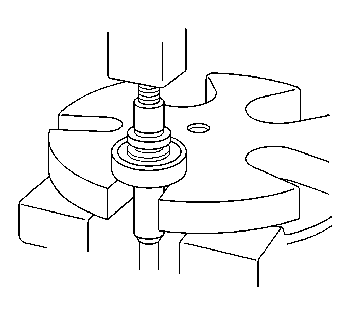
Important: Lubricate the new shaft bearing with power steering fluid prior to pressing
the new shaft bearing onto the shaft.
- Use an arbor press and a suitable spacer in order to press the new shaft
bearing onto the shaft.

- If the shaft bearing (17)
was removed, install the snap ring (15) on the shaft (18).
- Install the O-ring (13) into the front cover (12).
Important: Lubricate the lips of the new seal (14) with petroleum jelly.
- Install a new shaft seal (14) into the pump housing (2) using an arbor
press and a suitable spacer.
- Install the retainer ring (16) on the shaft (18).
- Install the following components into the front cover (12):
| • | The bearing shaft assembly |
- Install the snap ring (20) into the front cover (12).
Important: Lubricate the rotor (8), ring (6), and the vanes (7) with power steering
fluid prior to assembly.
- Install the rotor (8) into the ring (6).

Important: Ensure that the rounded edges of the vanes contact the rotor.
- Install the vanes into the rotor.

- Align the marks on the
following components:
- Install the following components on the ring (2):
Notice: Use the correct fastener in the correct location. Replacement fasteners
must be the correct part number for that application. Fasteners requiring
replacement or fasteners requiring the use of thread locking compound or sealant
are identified in the service procedure. Do not use paints, lubricants, or
corrosion inhibitors on fasteners or fastener joint surfaces unless specified.
These coatings affect fastener torque and joint clamping force and may damage
the fastener. Use the correct tightening sequence and specifications when
installing fasteners in order to avoid damage to parts and systems.
- Install the pressure
plate (1) on the ring (2) with screws.
Tighten
Tighten the pressure plate screws to 8 N·m (71 lb in).
- Install the following components into the pump housing (2):

| • | The rotor assembly (7, 8) |
- Install both O-rings (10, 11) into the front cover (12).
- Install the front cover (12) on the pump housing (2).
Secure the front cover with the pump body bolts (1).
Tighten
Tighten the pump body bolts to 54 N·m (40 lb ft).
- Install the gear (21) on the shaft (18) using the washer nut (22).
Disassemble Procedure (Control Valve)
Important: Do not disassemble the pressure relief valve unless the system pressure
is incorrect. Refer to
Power Steering System Test
.
Important: Do not disassemble the pressure relief valve unless it is absolutely
necessary. It is difficult to hold the valve body while removing the valve
plug. This increases the possibility of damaging the valve body.
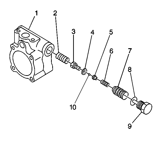
- Secure the pump.
- Remove the following components from the pump:
Notice: Always protect the pressure relief valve body when securing the valve
body. Following this instruction can help you avoid damage to the valve body.
- Remove the following components from the pump housing (1):
- Secure the valve body (7).
Important: Note the number of shims (4) that are removed from the pressure relief
valve.
- Remove the following components from the valve body (7):
- Remove the ball (10) from the valve body (7).
- Remove the following components from the valve body (7):
Assemble Procedure

- Install the following
components into the valve body (7):
| 1.1. | The retainer spring (6) |
Important: Be certain to install all of the shims which were removed.
- Install the shims (4) into the valve body (7).
Notice: Always protect the pressure relief valve body when securing the valve
body. Following this instruction can help you avoid damage to the valve body.
- Secure the valve body (7).
Notice: Use the correct fastener in the correct location. Replacement fasteners
must be the correct part number for that application. Fasteners requiring
replacement or fasteners requiring the use of thread locking compound or sealant
are identified in the service procedure. Do not use paints, lubricants, or
corrosion inhibitors on fasteners or fastener joint surfaces unless specified.
These coatings affect fastener torque and joint clamping force and may damage
the fastener. Use the correct tightening sequence and specifications when
installing fasteners in order to avoid damage to parts and systems.
- Install the valve
plug (3)
Tighten
Tighten the valve body plug to 54 N·m (40 lb ft).
- Install the following components into the pump housing (1):
| 5.1. | The valve spring (2) |
Power Steering Pump Disassemble LG4 with JE4
Disassemble Procedure
- Clean the exterior of the power steering pump with a suitable
cleaning solvent that will not damage the rubber components.
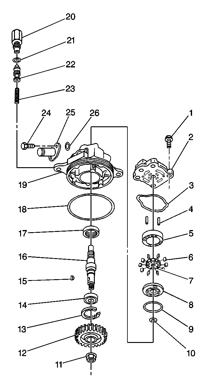
- Remove the following components
from the shaft:
| • | The gear (2) (the gear is a slip fit) |
- Remove the pump body bolts (1).
- Remove the rear cover (2) and gasket (3) from the pump body (19).
- Remove the side plate( 12) and ring (5) assembly.
- Dissemble the following components:
- Remove the snap ring (13) from the pump body.

Important: Gently tap with a plastic mallet on the end opposite the drive end to
remove the shaft from the pump body.
- Remove the shaft from the pump body.
- Remove the shaft seal from the pump body.

- Remove the O-ring from the pump body.
Inspection Procedure

- Inspect the bushing for
the following conditions:
| | Important: The bushing is not serviced.
If the bushing shows abnormal conditions, the rear cover must be replaced
(2).
|
- Use a suitable solvent in order to clean all of the parts.
Dry all of the parts.
- Inspect the vane tips (6) for the following conditions:
- Inspect the inner surface of the ring (5) for the following conditions:

Important: The vanes must fit properly in the rotor slots, without sticking or
excessive play.
- Inspect the fit of the vanes in the rotor.
- Inspect for the following conditions:
| • | Burrs in the rotor slots |
| • | Excessive wear at the thrust faces |
- Replace the rotor, the ring, and all the vanes if any of the following
conditions are present:

- Inspect the side plate
(8) and rear cover for wear at the thrust faces.
- Replace the side plate (8) and the rear cover (2) if wear is excessive.
- Inspect the shaft (16) for the following conditions:
Important: Replace the rear cover (2) whenever a shaft replacement is necessary.
- Secure the pump body (19).
- Remove the connector (20) and the O-ring (21).
- Remove the valve body (22) and spring (23).

- Inspect the shaft bearing
. Refer to
Wheel Bearings Diagnosis
.
- If the shaft or bearing needs to be replaced, perform the following
steps:
| • | Press the shaft bearing off of the shaft using an arbor press |
| • | Discard the shaft bearing |
Assembly Procedure

Important: Lubricate the new bearing with power steering fluid prior to pressing.
- Press the new bearing on to the shaft using an arbor press.

- Install the O-ring (18)
into the pump body (19).
Important: Lubricate the lips of the new seal (17) with petroleum jelly.
- Install a new shaft seal (17) into the pump housing (19) using an arbor
press and a suitable spacer.
- Install the shaft bearing assembly (14, 16) into the pump housing
(19).
- Install the retainer ring (13) into the pump housing (19).
Important: Lubricate the rotor (7), ring (5) and the vanes (6) with power steering
fluid prior to assembly.
- Install the rotor (7) into the ring (5).

Important: Ensure that the rounded edges of the vanes contact the rotor.
- Install the vanes into the rotor.
- Install the O-rings into the pump body.

- Install the following components into the pump housing (19):
Notice: Use the correct fastener in the correct location. Replacement fasteners
must be the correct part number for that application. Fasteners requiring
replacement or fasteners requiring the use of thread locking compound or sealant
are identified in the service procedure. Do not use paints, lubricants, or
corrosion inhibitors on fasteners or fastener joint surfaces unless specified.
These coatings affect fastener torque and joint clamping force and may damage
the fastener. Use the correct tightening sequence and specifications when
installing fasteners in order to avoid damage to parts and systems.
- Install the rear
cover (2) and gasket (3) to the pump housing (19) with the rear cover bolts
(1).
Tighten
Tighten the rear cover bolts to 21 N·m (15 lb ft).
- Install the valve spring (23) and valve body (22) into the pump
housing (19).
- Install the O-ring (21) and connector (20) into the pump housing
(19).
Tighten
Tighten the connector to 49 N·m (36 lb ft).
- Install the following components:
| 13.3. | The washer nut (11) |
Tighten
Tighten the gear mounting nut to 450 N·m (330 lb ft).


