Removal Procedure
Tools Required
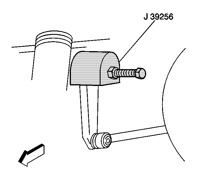
| • | J 39256 Pitman Arm Puller |
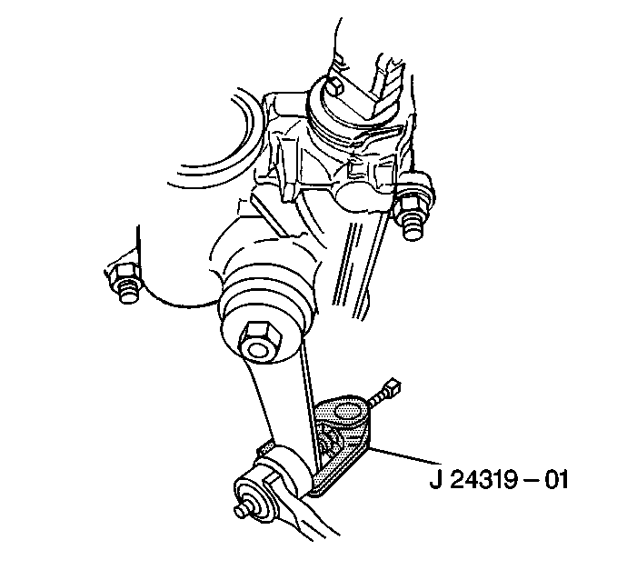
| • | J 24319-01 Steering Linkage Puller |
- Position the front wheels and the steering wheel straight ahead.
- Tilt the cab. Refer to Cab Tilting in General Information.
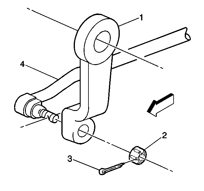
- Remove the cotter pin (3).
- Discard the cotter pin.
- Remove the relay rod nut (2).
- Mark the position of the pitman arm (1) on the pitman shaft.
- Use the J 24319-01 in order to remove the relay rod end from the pitman arm end.
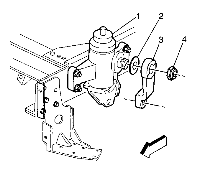
- Remove the pitman arm nut (4).
- Use the J 39256 in order to remove the pitman arm (3) from the pitman arm shaft .
Notice: Do not hammer on the pitman arm, pitman arm shaft, or puller. Damage to the pitman or steering gear may result. Pitman arms are non-repairable and must be replaced when damaged or worn.


Installation Procedure
- Install the pitman arm (3) on the pitman shaft.
- Install the pitman arm nut (4) .
- Install the relay rod (4).
- Install the relay rod nut (2).
- Advance the relay rod nuts to the nearest cotter pin slot.
- Install the new cotter pin (3).
- Lower the cab.
Important: Align the position marks made during removal on the pitman arm and the pitman shaft.

Notice: Use the correct fastener in the correct location. Replacement fasteners must be the correct part number for that application. Fasteners requiring replacement or fasteners requiring the use of thread locking compound or sealant are identified in the service procedure. Do not use paints, lubricants, or corrosion inhibitors on fasteners or fastener joint surfaces unless specified. These coatings affect fastener torque and joint clamping force and may damage the fastener. Use the correct tightening sequence and specifications when installing fasteners in order to avoid damage to parts and systems.
Tighten
Tighten the pitman arm nut to 370 N·m (275 lb ft).

Notice: Use the correct fastener in the correct location. Replacement fasteners must be the correct part number for that application. Fasteners requiring replacement or fasteners requiring the use of thread locking compound or sealant are identified in the service procedure. Do not use paints, lubricants, or corrosion inhibitors on fasteners or fastener joint surfaces unless specified. These coatings affect fastener torque and joint clamping force and may damage the fastener. Use the correct tightening sequence and specifications when installing fasteners in order to avoid damage to parts and systems.
Tighten
Tighten the relay rod nut to 160 N·m (120 lb ft).
