The cab replacement procedure will vary depending upon
the optional equipment on the vehicle. Some steps required due to optional
equipment have been included, but be sure to check the vehicle for any
special steps it may require. The following procedures are intended to
be used only as a guide.
Caution: Unless directed otherwise, the ignition and start switch must be in the OFF or LOCK position, and all electrical loads must be OFF before servicing
any electrical component. Disconnect the negative battery cable to prevent an electrical spark should a tool or equipment come in contact with an exposed electrical terminal. Failure to follow these precautions may result in personal injury and/or damage to
the vehicle or its components.
Important:
| • | Tag all lines, wires, hoses and harnesses during removal for proper
location during installation. |
- Disconnect the negative battery cable. Refer to
Battery Cable Replacement
.
- Open the hood.
- Remove the grille. refer to
Grille Replacement
.
- Remove the left and the right headlamp assemblies. Refer to
Headlamp Replacement
.
- Recover the air conditioning refrigerant. Refer to Refrigerant Recovery and Recharging
.
- Remove the air conditioning pipes and the brackets. Refer to Evaporator Hose Assembly Replacement (LG5)
.
- Drain the coolant.
- Remove the heater hoses. Refer to Heater Pipes
Replacement (LG5 Inlet )
or Heater Pipes Replacement
(LG4 Inlet)
.
- Remove the ground strap.
- Remove the main wire harness under the hood.
- Remove the clutch fluid pipe (if equipped).
- Disconnect the transmission control cables.
- Disconnect the parking brake cable. Refer to
Park Brake Cable Replacement
.
- Tilt the cab. Refer to
Cab Tilting
in General Information.
- Remove the air brake hoses
(if equipped) or the linkage to the brake master cylinder.
- Remove the steering shaft at the steering gear. Mark the shaft
and the gear in order to aid in reassembly. Refer to
Lower Steering Shaft Assembly Replacement
.
- Remove the cab lock cover.
- Fasten a rope securely to the cab lock. Use a hoist or chain block
in order to keep the cab tilted.
- Remove the torsion bar levers.
- Remove the cab tilt support.
- Lower the cab. Refer to
Cab Tilting
in General Information.
- Remove each center pin by tapping with a hammer, while lowering
the cab slowly.
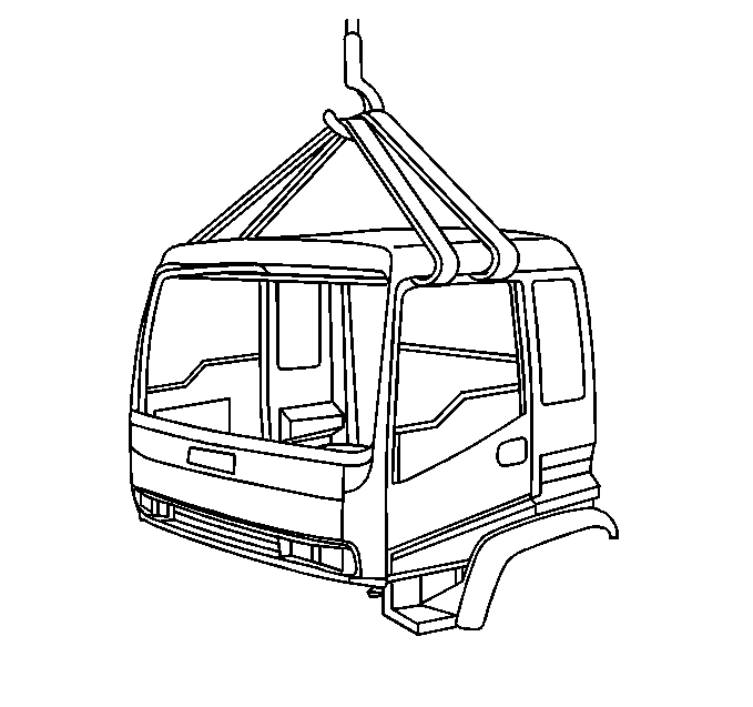
Notice: When the cab is being removed, ensure that the lifting straps are not
wrapped around the door frames. Otherwise, damage to the window
channels may occur.
- Perform the following procedure in order to remove the cab from the
chassis. Keep in mind that the trimmed cab weighs about 1,000 lbs.
| 23.1. | Use four commercial straps that are 6 inches wide and about
10 feet long in order to lift the cab from the chassis. |
| 23.2. | Open the doors. Pass the straps into the cab through the door
opening on each side through the rear of the cab. |
| 23.3. | Connect the straps in the center. |
- Walk around the cab in order to make sure all components have
been disconnected from the chassis.
- Raise the cab slowly. Use the aid of a helper in order to guide
the cab while the cab is being lifted.
Installation Procedure
- Block the chassis wheels.
Notice: When the cab is being removed, ensure that the lifting straps are not
wrapped around the door frames. Otherwise, damage to the window
channels may occur.
- Perform the following procedure in order to install the cab onto the
chassis. Keep in mind that the trimmed cab weighs about 1,000 lbs.
| 2.1. | Use four commercial straps that are 6 inches wide and about
10 feet long in order to lift the cab from the chassis. |
| 2.2. | Open the doors. Pass the straps into the cab through the door
opening on each side through the rear of cab. |
| 2.3. | Connect the straps in the center. |
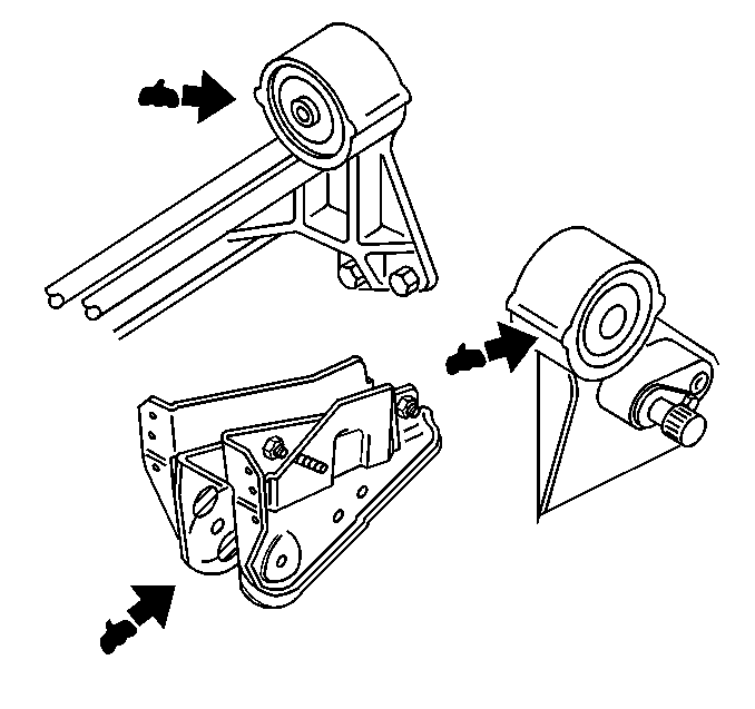
- Apply grease to the following
areas of the cab mounts:
| • | The circumference area of the bracket where the washer comes in
contact |
| • | The bushing inner surface in the side where the sleeve is inserted |
| • | At least two areas on both inside surfaces of the bracket where
the washer comes in contact |
- Install the left and the
right center pins.
- Perform the following procedure:
| 5.1. | Hook a wire to the cab striker. |
| 5.2. | Pull the safety lever. |
| 5.3. | Tilt the cab slowly. |
| 5.4. | Use the wire in order to keep the cab from floating up. |
Notice: Use the correct fastener in the correct location. Replacement fasteners
must be the correct part number for that application. Fasteners requiring
replacement or fasteners requiring the use of thread locking compound or sealant
are identified in the service procedure. Do not use paints, lubricants, or
corrosion inhibitors on fasteners or fastener joint surfaces unless specified.
These coatings affect fastener torque and joint clamping force and may damage
the fastener. Use the correct tightening sequence and specifications when
installing fasteners in order to avoid damage to parts and systems.
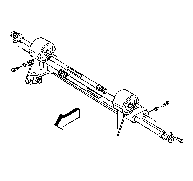
- Extend the cab support
and lock it into position.
Tighten
Tighten the bolts to 68 N·m (50 lb ft).
- Perform the following in order to install the torsion bar levers.
| • | Locate the left and right identification marks before installation. |
| • | Install the torsion bar levers. |
Tighten
Tighten the bolt/nut to 37 N·m (27 lb ft).
- Use the match marks made during disassembly as a guide in order
to apply grease to the steering shaft.
- Insert the steering shaft on the steering unit. Refer to
Lower Steering Shaft Assembly Replacement
.
- Tighten the key bolt.
Tighten
Tighten the bolts to 61 N·m (45 lb ft).
- Connect the throttle cable.
- Connect the transmission cables. Refer to
Shift Cable Replacement
.
- Connect the air brake hoses (if equipped) or the linkage to the
brake master cylinder.
- Connect the parking brake cable. Refer to
Park Brake Cable Replacement
.
- Lower the cab.
- Install the clutch fluid pipe (if equipped).
- Install the main wire harness under the hood.
- Install the ground strap.
- Install the heater hoses. Refer to Heater Pipes
Replacement (LG5 Outlet)
or Heater Pipes Replacement
(LG4 Outlet )
.
- Install the left and the right headlamp assemblies. Refer to
Headlamp Replacement
.
- Install the grille. Refer to
Grille Replacement
.
- Connect the negative battery cable. Refer to
Battery Cable Replacement
.
- Recharge the air conditioning refrigerant to specification. Refer
to Refrigerant Recovery and Recharging
.
- Refill the engine coolant to proper level. Refer to
Fluid and Lubricant Recommendations
.
- Bleed the clutch system.
