Strategy-Based Diagnostics
The strategy-based diagnostic is a uniform approach to repair all electrical/electronic (E/E) systems. The diagnostic flow can always be used to resolve an E/E system problem and is a starting point when repairs are necessary. The following steps will instruct the technician how to proceed with a diagnosis:
- Verify the customer complaint.
- Perform preliminary checks.
- Check bulletins and other service information.
- Refer to service information (manual) system checks.
- Refer to service diagnostics.
To verify the customer complaint, the technician should know the normal operation of the system.
| • | Conduct a thorough visual inspection. |
| • | Review the service history. |
| • | Detect unusual sounds or odors. |
| • | Gather diagnostic trouble code information to achieve an effective repair. |
This includes videos, newsletters, etc.
| • | System checks contain information on a system that may not be supported by one or more DTCs. |
| • | System checks verify proper operation of the system. This will lead the technician in an organized approach to diagnostics. |
DTC Stored
Follow the designated DTC chart exactly to make an effective repair.
No DTC
Select the symptom from the symptom tables. Follow the diagnostic paths or suggestions to complete the repair. You may refer to the applicable component/system check in the system checks.
No Matching Symptom
- Analyze the complaint.
- Develop a plan for diagnostics.
- Utilize the wiring diagrams and the theory of operation.
Call technical assistance for similar cases where repair history may be available. Combine technician knowledge with efficient use of the available service information.
Intermittents
Conditions that are not always present, are called intermittents. To resolve intermittents, perform the following steps:
- Observe history DTCs and DTC modes.
- Evaluate the symptoms and the conditions described by the customer.
- Use a check sheet or other method to identify the circuit or electrical system component.
- Follow the suggestions for intermittent diagnosis found in the service documentation.
Most scan tools have data-capturing capabilities that can assist in detecting intermittents.
No Trouble Found
This condition exists when the vehicle is found to operate normally. The condition described by the customer may be normal. Verify the customer complaint against another vehicle that is operating normally. The condition may be intermittent. Verify the complaint under the conditions described by the customer before releasing the vehicle.
- Re-examine the complaint.
- Repair and verify.
| • | When the complaint cannot be successfully found or isolated, a re-evaluation is necessary. |
| • | The complaint should be re-verified and could be intermittent as defined in Intermittents, or could be normal. |
| • | After isolating the cause, the repairs should be made. |
| • | Validate for proper operation and verify that the symptom has been corrected. |
| • | This may involve road testing or other methods to verify that the complaint has been resolved under the conditions noted by the customer. |
OBD Serviceability Issues
The list of non-vehicle faults that could affect the performance of the OBD system has been compiled. These non-vehicle faults vary from environmental conditions to the quality of fuel used.
The illumination of the malfunction indicator lamp (MIL) due to a non-vehicle fault could lead to misdiagnosis of the vehicle, increased warranty expense and customer dissatisfaction. The following list of non-vehicle faults does not include every possible fault and may not apply equally to all product lines.
Poor Vehicle Maintenance
The sensitivity of OBD diagnostics will cause the MIL to turn ON if the vehicle is not maintained properly. Restricted air filters, fuel filters, and crankcase deposits due to lack of oil changes or improper oil quality can trigger actual vehicle faults that were not previously monitored prior to OBD. Poor vehicle maintenance can not be classified as a non-vehicle fault, but with the sensitivity of OBD diagnostics, vehicle maintenance schedules must be more closely followed.
Maintenance Schedule
Refer to Maintenance Schedule in Maintenance and Lubrication.
Visual/Physical Engine Compartment Inspection
Perform a careful visual and physical engine compartment inspection when performing any diagnostic procedure or diagnosing the cause of an emission test failure. This can often lead to repairing a problem without further steps. Use the following guidelines when performing an inspection:
| • | Inspect all of the vacuum hoses for punches, cuts, disconnects, and correct routing. |
| • | Inspect the hoses that are difficult to see behind other components. |
| • | Inspect all of the wires in engine compartment for proper connections, burned or chafed spots, pinched wires, contact with sharp edges or contact with hot exhaust manifolds or pipes. |
Basic Knowledge of Tools Required
Important: Lack of basic knowledge of this powertrain when performing diagnostic procedures could result in an incorrect diagnosis or damage to powertrain components. Do not attempt to diagnose a powertrain problem without this basic knowledge.
A basic understanding of hand tools is necessary to effectively use this section.
Passive and Active Diagnostic Tests
A passive test is a diagnostic test which simply monitors a vehicle system or component. Conversely, an active test takes some sort of action when performing diagnostic functions, often in response to a failed passive test.
Intrusive Diagnostic Tests
This is any on-board test run by the Diagnostic Management System which may have an effect on vehicle performance or emission levels.
Warm-Up Cycle
A warm-up cycle means that engine temperature must reach a minimum of 70°C (160°F) and rise at least 22°C (40°F) over the course of a trip.
Diagnostic
A diagnostic is simply a test run on a system or component to determine if the system or component is operating according to specification.
Enable Criteria
Enable criteria is the conditions necessary for a given diagnostic test to run. Each diagnostic has a specific list of conditions which must be met before the diagnostic will run.
The Diagnostic Executive
The Diagnostic Executive is a segment of software which is designed to coordinate and prioritize the diagnostic procedures as well as define the rules for recording and displaying their results. The main responsibilities of the Diagnostic Executive are listed as following:
| • | Commanding the MIL ON and OFF |
| • | DTC logging and clearing |
| • | Current status information on each diagnostic |
| • | System Status |
Diagnostic Information
The diagnostic charts and functional checks are designed to locate a faulty circuit or component through a process of logical decisions. The charts are prepared with the requirement that the vehicle functioned correctly at the time of assembly and that there are not multiple faults present.
There is a continuous self-diagnosis on certain control functions. This diagnostic capability is complemented by the diagnostic procedures contained in this manual. The language of communicating the source of the malfunction is a system of diagnostic trouble codes. When a malfunction is detected by the control module, a diagnostic trouble code is set and the malfunction indicator lamp (MIL) is illuminated.
Malfunction Indicator Lamp (MIL)
The malfunction indicator lamp (MIL) looks the same as the MIL you are already familiar with (Check Engine Soon lamp if so equipped). However, OBD requires that the MIL illuminates under a strict set of guide lines.
The MIL is turned ON when the ECM detects a DTC that will impact the vehicle emissions and performance.
Extinguishing the MIL
Connect the memory clear switch for one to two seconds then disconnect the memory clear switch.
Data Link Connector (DLC)

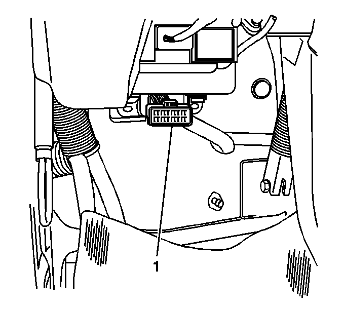
The provision for communication with the control module is the data link connector (DLC). The DLC (1) is located at the lower left of the instrument panel behind a small square cover.
The DLC connects to a scan tool. Some common uses of the scan tool are listed below:
| • | Identifying stored diagnostic trouble codes (DTCs). |
| • | Clearing DTCs. |
| • | Performing output control tests. |
| • | Reading serial data. |
Verifying Vehicle Repair
Following a repair, the technician should perform the following steps:
- Review and record the Failure Records for the DTC which has been diagnosed.
- Clear the DTCs.
- Operate the vehicle within the conditions noted in the Failure Records.
- Monitor the DTC status information for the specific DTC which has been diagnosed until the diagnostic test associated with that DTC runs.
Following these steps are very important in verifying repairs on OBD systems. Failure to follow these steps could result in unnecessary repairs.
Reading Diagnostic Trouble Codes Using A Tech 2 or Other Scan Tool
The procedure for reading diagnostic trouble code (DTC) is to use a diagnostic scan tool. When reading DTCs, follow instructions supplied by tool manufacturer.
Clearing Diagnostic Trouble Codes
Important: Do not clear DTCs unless directed to do so by the service information provided for each diagnostic procedure. When DTCs are cleared, the Failure Record data which may help diagnose an intermittent fault will also be erased from memory.
To clear diagnostic trouble codes (DTCs), use the diagnostic scan tool clear DTC information function. Follow the instructions supplied by the tool manufacturer.
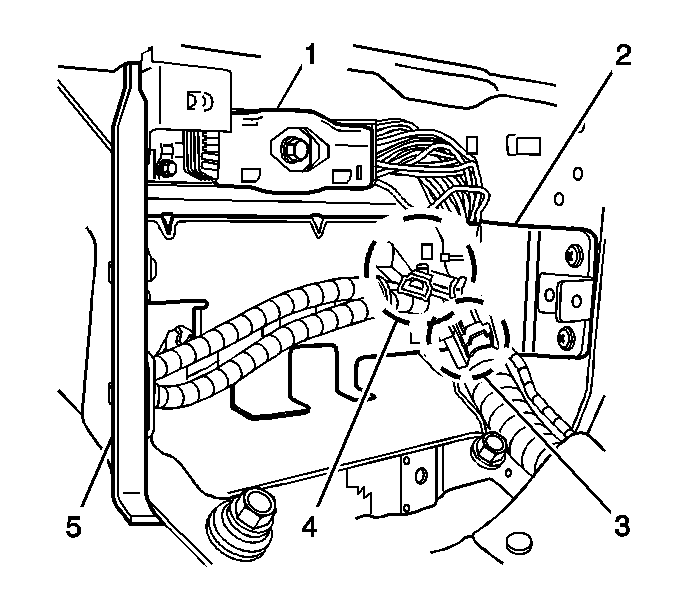
When a scan tool is not available, DTCs can also be cleared by connecting the memory clear switch connectors (4) for 1-2 seconds, then disconnecting the memory clear switch connectors located under the dash.

Vehicle Type: WT 5500.
OR
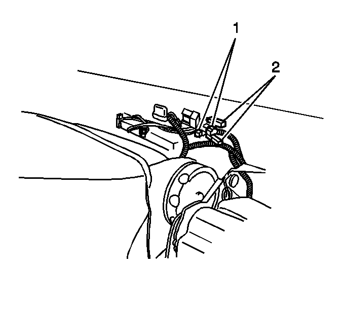
When a scan tool is not available, DTCs can also be cleared by connecting the memory clear switch connectors (1) for 1-2 seconds, then disconnecting the memory clear switch connectors Located under right seat.

Vehicle Type: T6500, T7500, T8500.
Tech 2 Scan Tool
General Motors (GM) recommend to use Tech 2. Refer to Tech 2 scan tool user guide.
