The engine control module (ECM) is located in the passenger compartment below the right seat. The ECM controls the following:
| • | The fuel system |
| • | The ignition timing |
| • | The on-board diagnostics for powertrain functions |
The ECM constantly observes the information from various sensors. The ECM controls the systems that affect vehicle performance. The ECM performs the diagnostic function of the system. The ECM can recognize operational problems, alert the driver through the malfunction indicator lamp (MIL), and store diagnostic trouble codes (DTCs). DTCs identify the system faults to aid the technician in making repairs.
ECM Function
The ECM supplies 5-12 volts to power various sensors or switches. The power is supplied through resistances in the ECM which are so high in value that a test lamp will not illuminate when connected to the circuit. In some cases, even an ordinary shop voltmeter will not give an accurate reading because the voltmeter resistance is too low. Therefore, a DMM with at least 10-megaohms input impedance is required to ensure accurate voltage readings. The DMM meets this requirement. The ECM controls output circuits such as the injectors, idle speed control (ISC), etc., by controlling the ground or the power feed circuit through transistors or through either of the following two devices:
| • | Output driver modules (ODM) |
| • | Quad driver module (QDM) |
ECM Voltage Description
The ECM supplies a buffered voltage to various switches and sensors. The ECM can do this because resistance in the ECM is so high in value that a test lamp may not illuminate when connected to the circuit. An ordinary shop voltmeter may not give an accurate reading because the voltmeter input impedance is too low. Use a 10-megaohm input impedance DMM, to ensure accurate voltage readings.
The input and/or output devices in the ECM include analog-to-digital converters, signal buffers, counters, and special drivers. The ECM controls most components with electronic switches which complete a ground circuit when turned ON. These switches are arranged in groups of four and seven, called either a surface-mounted QDM, which can independently control up to four output terminals, or QDMs which can independently control up to seven outputs. Not all outputs are always used.
ECM Service Precautions
The ECM is designed to withstand normal current draws associated with vehicle operation. Avoid overloading any circuit. When testing for opens and shorts, do not ground or apply voltage to any of the ECM circuits unless instructed to do so. These circuits should only be tested using a DMM. The ECM should remain connected to the ECM harness or to a recommended breakout box.
Aftermarket Electrical and Vacuum Equipment
Aftermarket or add-on electrical and vacuum equipment is defined as any equipment which connects to the vehicle's electrical or vacuum systems that is installed on a vehicle after the vehicle leaves the factory. No allowances have been made in the vehicle design for this type of equipment.
No add-on vacuum equipment should be added to this vehicle.
Add-on electrical equipment must only be connected to the vehicle's electrical system at the battery power and ground.
Add-on electrical equipment, even when installed to these guidelines, may still cause the powertrain system to malfunction. This may also include equipment not connected to the vehicle electrical system such as portable telephones and radios. Therefore, the first step in diagnosing any powertrain fault is to eliminate all aftermarket electrical equipment from the vehicle. After this is done, if the fault still exists, the fault may be diagnosed in the normal manner.
Electrostatic Discharge Damage
Electronic components used in the ECM are often designed to carry very low voltage. Electronic components are susceptible to damage caused by electrostatic discharge. By comparison, as much as 4,000 volts may be needed for a person to feel even the zap of a static discharge.
There are several ways for a person to become statically charged. The most common methods of charging are by friction and induction.
| • | An example of charging by friction is a person sliding across a vehicle seat. |
Important: To prevent possible electrostatic discharge damage, follow these guidelines:
|
| • | Charge by induction occurs when a person with well insulated shoes stands near a highly charged object and momentarily touches ground. Charges of the same polarity are drained off leaving the person highly charged with opposite polarity. |
Supply Pump
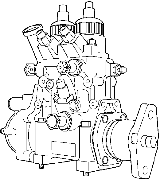
The supply pump is comprised of the pump proper, feed pump, and coupling.
Engine output transmitted to the idle gear, air compressor, and drive gear and is transmitted through coupling to the camshaft of supply pump.
The plunger is lubricated and cooled with fuel. Do not use any fuel other than the type specified.
The supply pump unit is comprised of the same feed system as is used in the conventional duplex pump and two cylinders each having a pressure control valve (PCV). Using a triple action cam has reduced the number of pump cylinders required to one third of the number of engine cylinders (2 cylinder pump in case of 6 cylinder engine). Further, the number of times of feeding to common rail is equal to that of injection, giving smooth, stable common rail pressure.
Pressure Control Valve (PCV)
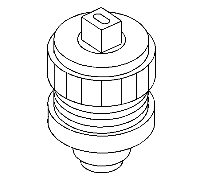
The PCV is used to adjust supply pump discharge amount so as to adjust common rail pressure. Discharge amount from the supply pump to the common rail is determined by continuity timing to PCV.
Feed Pump
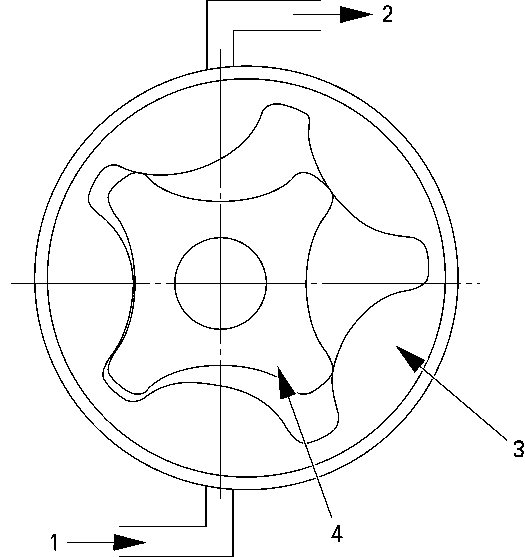
The feed pump is built in the supply pump to pump fuel up and supply fuel through fuel filter into the supply pump unit. Feed pump inside rotor (4) is driven by supply pump camshaft. When the inside rotor starts to rotate, the outside rotor also rotates together with inside rotor. The outside rotor (3) has one more tooth than the inside rotor, therefore, the inside rotor tooth slides on the face of the inside tooth in the outside rotor during rotation. The fuel hold clearance between the outside rotor and the inside rotor tooth causes fuel to be pushed out of the discharge port (2).
Coupling
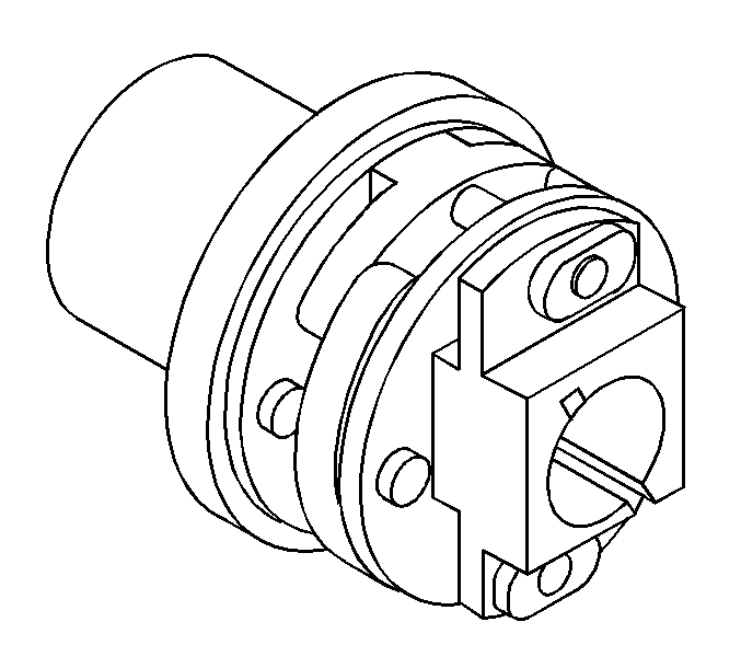
The coupling is a laminated type, serving to transmit the driving torque from the engine side of the camshaft to the supply pump.
Pump Position Camshaft Sensor
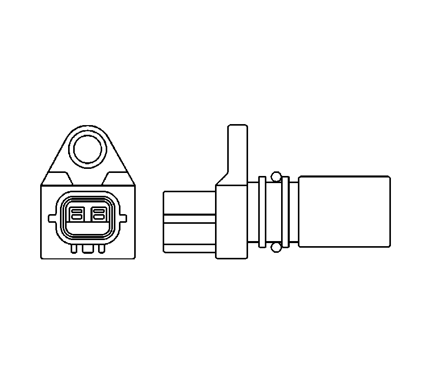
The CAM sensor is installed at the side of the supply pump. The sensor distinguishes the cylinders of the engine. In case of crankshaft position (CKP) sensor trouble, the CAM sensor backs up the detection of engine speed.
This CAM sensor comprises the same parts as in CKP sensor. However, the number of turns of the CAM sensor coil is different from that of CKP sensor, and the CAM sensor is installed to the supply pump.
With the engine started, the pulse notches that are in the middle of the supply pump camshaft will interrupt the magnetic field made by the sensor magnet, thereby generating alternating current.
The pulse notches occur every 60 degrees of camshaft, every 120 degrees of crank angle, with one extra tooth.
Therefore, seven pulses are output per one rotation of camshaft, 2 rotations of the engine. The pulse output by the surplus tooth is recognized as engine cylinder number 1 reference pulse.
Common Rail
The common rail is installed on the intake manifold. The common rail is equipped with flow damper, pressure limiter, and common rail pressure sensor.
The common rail unit has a common fuel passage, fuel passage holes, and installing threaded holes. The common fuel passage is a through hole made in the common rail unit. The common rail pressure sensor is installed at the left end of the unit.
Flow Damper
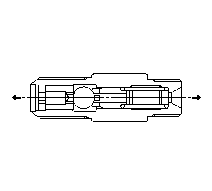
The flow damper comprises a piston, ball, spring seat, and spring.
The flow damper is used to damp the pressure pulsating in the common rail and the injection pipe.
During driving the flow of fuel makes the piston, ball, and spring seat move a little to the injector side and float.
Should too much fuel pass the flow damper, the ball moves further toward the injector until the ball comes into contact with the seat surface of the flow damper unit, thereby shutting the fuel passages.
Pressure Limiter
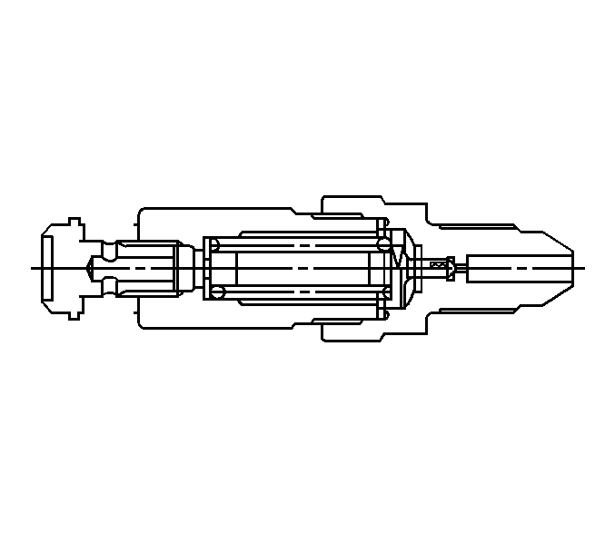
The pressure limiter opens when abnormally high pressure is generated, releasing the pressure. When the common rail pressure reaches approximately 140 MPa (1,420 kg/cm²), the pressure limiter is actuated (opens), and when the pressure drops to approximately 30 MPa (310 kg/cm²), the pressure limiter works to maintain the pressure.
Common Rail Pressure Sensor
The common rail pressure sensor, installed at left end of the common rail, serving the detect fuel pressure. The common rail pressure sensor is a semiconductor type pressure sensor. The sensor utilizes a silicon property, where the electric resistance of pressurized silicone is varied.
A special gasket is used at the connection with the common rail body so as to seal high pressure fuel.
Injector
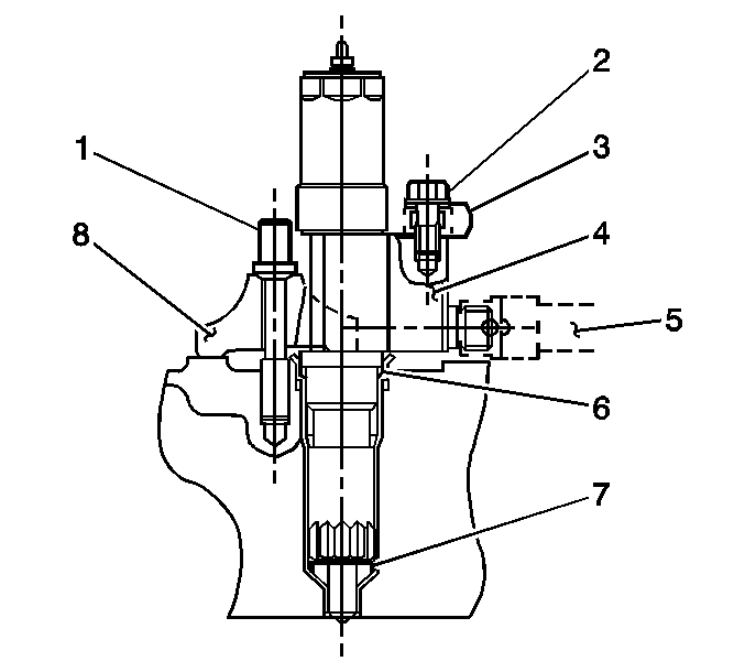
The injector comprises a two-way solenoid valve, hydraulic piston, and nozzle. The solenoid valve controls the injection amount, injection timing, and injection rate of fuel by controlling the pressure in the control chamber.
The nozzle (6) is a multihole type with a injection starting pressure (valve opening pressure) of 8.7 MPa (85 kg/cm²).
The injection body is clamped (7). The cylinder head injection part is provided with an O-ring (5) by which the entry of engine oil into the injector hole of the cylinder head is prevented.
Crank Position (CKP) Sensor
This sensor comprises a permanent magnet, coil, and iron core and is installed in the flywheel housing. With the engine started, the signal holes made on the outer periphery of the flywheel interrupt the magnetic field made by the magnet, thereby generating AC in the coil.
The signal holes on the flywheel are provided every 15 degrees, but one point is holeless. Therefore, the signal holes totals 23. Forty-six pulses are outputted per 2 rotations of the engine, one rotation of supply pump camshaft. By this signal, engine speed and 15 degree based crank angle can be detected.
Engine Coolant Temperature (ECT) Sensor
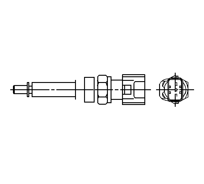
The engine coolant temperature (ECT) sensor is a thermister type installed on the thermostat case. Change in coolant temperature leads to a resistance change signal that is sent to ECM to optimize fuel injection control.
ECM applies voltage to the thermister and detects from the voltage divided between in ECM and thermister resistance values.
Fuel Rail Temperature (FT) Sensor
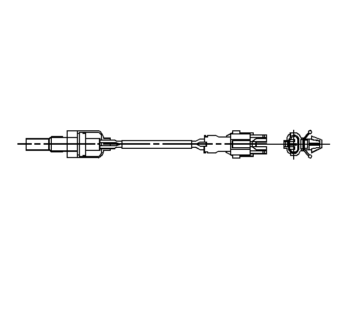
The FT sensor is a thermister type installed in the casing provided in the fuel return circuit.
Change in fuel temperature is changed into a resistance change signal and sent to ECM for optimization of fuel injection control.
Accelerator Sensor
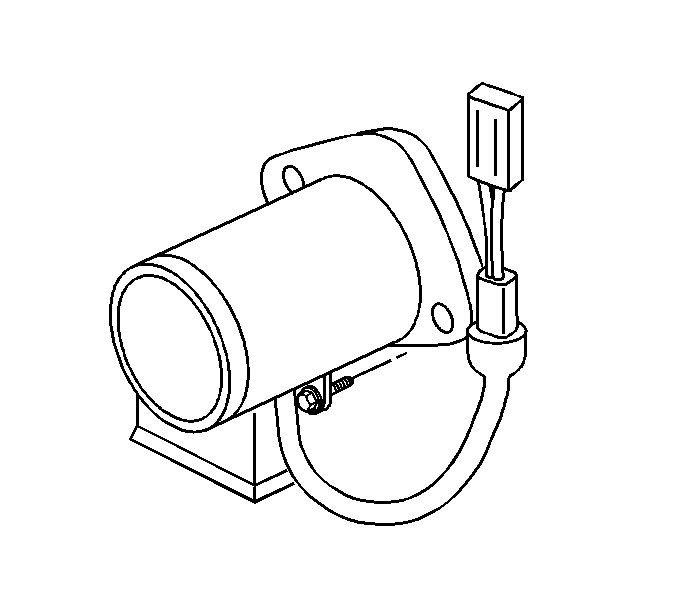
This sensor is a hall IC type substituting electric signals for accelerator pedaling amount to be sent to ECM. The sensor is connected to the accelerator pedal bracket assembly.
Boost Sensor
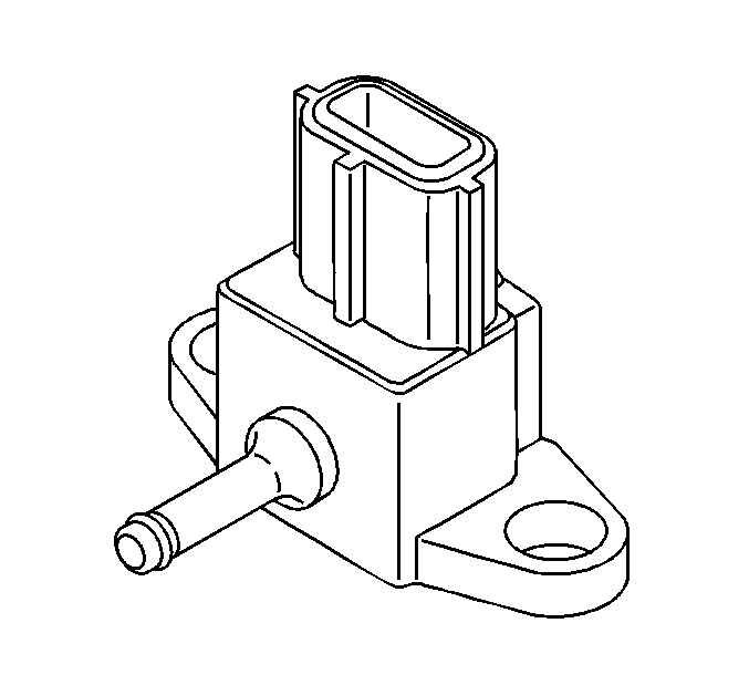
The boost sensor is fixed on the cab back frame and is connected to intake manifold by a vacuum hose.
The boost sensor generates voltage according to air aspiration pressure and generation voltage is input to ECM for boost sensor signal.
Ambient Air Temperature Sensor
The Ambient Air Temperature Sensor is located on the inside of the front cab panel.
The Ambient Air Temperature is changed into a resistance change signal and sent to ECM for optimization of fuel injection control.
Barometric Pressure (BARO) Sensor
The ATM pressure sensor is located in the ECM.
The ATM pressure sensor signal send to the ECM for optimization of fuel injection control under vehicle operation high.
