Parking Brake Adjustment Bendix 229 mm (9 in)
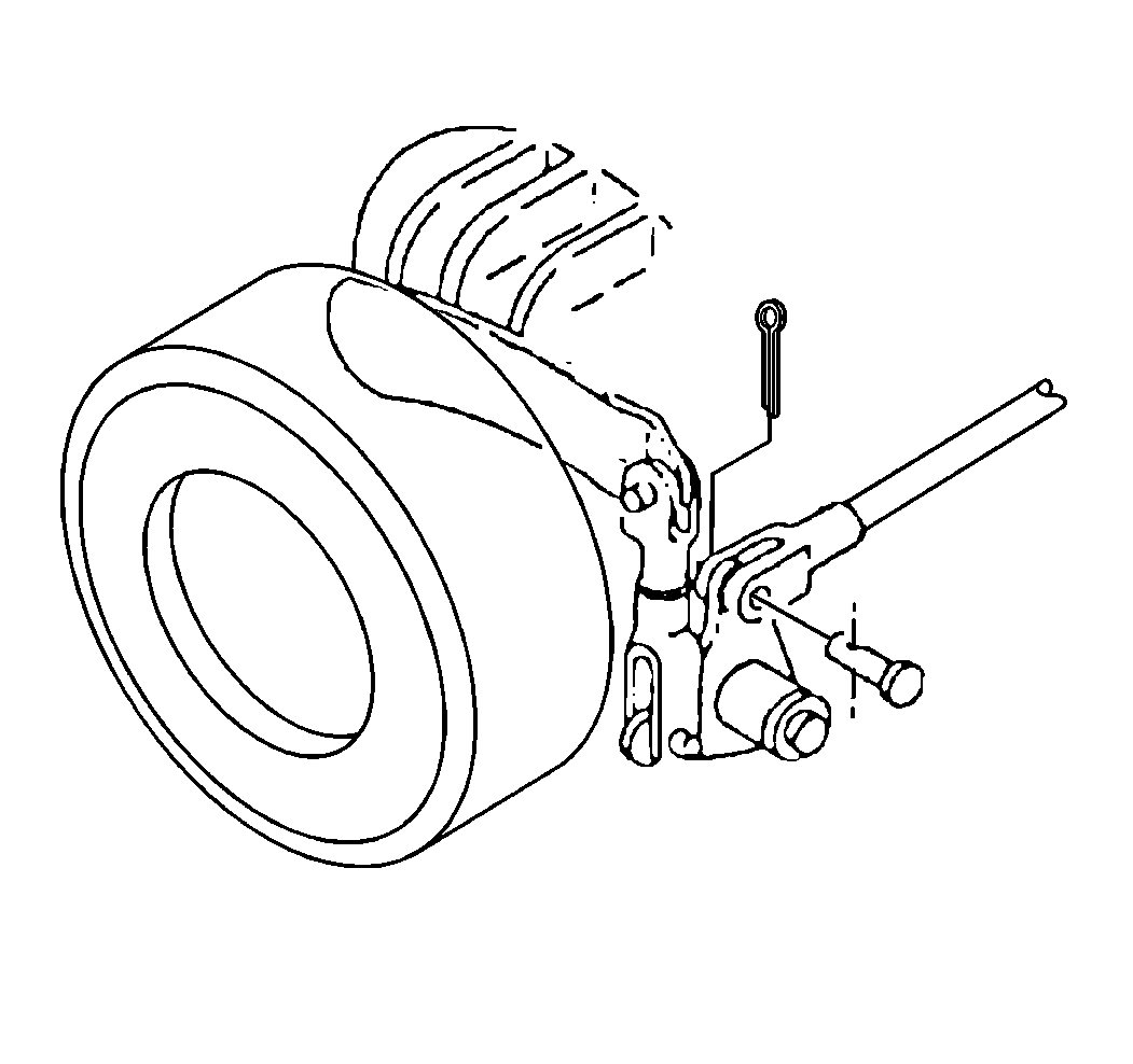
The Bendix® 229 mm (9 in) parking brake
assembly does not have a brake shoe adjusting screw. Adjustment is done at
the cam lever clevis.

- Block the vehicle wheels.
- Fully release the parking brake.
- Remove the cotter pins.
- Remove the clevis pins.
- Slide the clevis from the cam lever.
- Move the cam lever slightly upward in order to take up the slack
between the cam and the brake shoe web.
- Adjust the clevis in or out in order to align the clevis with
the hole in the cam lever.
- Install the clevis.
- Install the clevis pin.
- Install the cotter pin.
- Remove the wheel blocks.
- Apply the parking brake and note the parking brake's holding ability
in order to verify the operation.
- Fully release the parking brake and check that the linings are
completely free of the drum.
- Repeat the procedure, if necessary.
Parking Brake Adjustment Bendix 305 mm (12 in)

- Block the wheels.
- Fully release the parking brake.
- Jack up at least one rear wheel.
- Remove the cotter pin and the clevis pin from the operating lever
clevis in order to allow freedom for the full release of the linings.
- Insert a 0.25 mm (0.010 in) feeler gage between
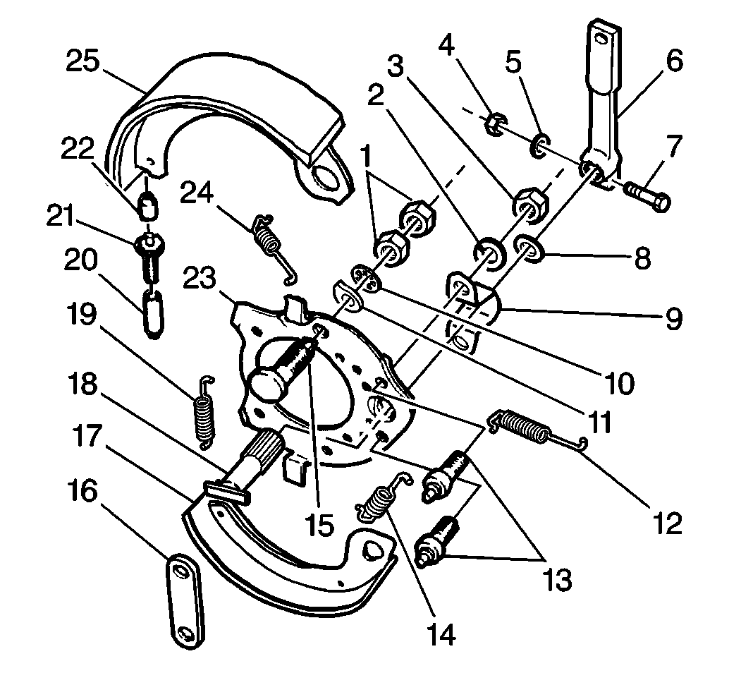
the top lining (25) and the drum near the center of the lining.
- From the forward side (toward the engine) at the top of the support
plate (23), turn the hex head of the adjusting eccentric (15) counterclockwise
until the feeler gage fits snugly between the lining (25) and the
drum.
- If the preload tension of the curved spring washer (11)
on the shoe adjusting eccentric is not enough to hold the adjustment, perform
the following procedure:
| 7.3. | Adjust the two nuts (1) until the preload on the curved spring
washer (11) creates a drag of 6 N·m (55 lb in)
when the shoe adjusting eccentric (15) turns beyond one complete revolution. |
| 7.4. | Tighten the inboard nut in order to increase the preload. |
| 7.5. | Tighten the outboard nut in order to the lock setting. |
| 7.6. | Install the linings (17, 25). |
| 7.7. | Adjust the shoe adjusting eccentric (15). |
| 7.8. | Drive the knock-out plugs from the drum. |
- Adjust the parking brake linkage before connecting the clevis.
- Expand the linings by turning the adjusting screw star wheel using
a screwdriver inserted through the access hole in the drum.
| 9.1. | Move the outer end of the screwdriver away from the propeller
shaft. |
| 9.2. | Insert a 0.25 mm (0.010 in) feeler gage between
the lower lining (17) and the drum near the center of the lining (17). |
| 9.3. | Adjust the linings until the feeler gage fits snugly. |
- Ensure that the parking brake is fully released.
- Move the operating lever (1) counterclockwise (toward the parking
brake cable) until the camshaft (2) is snug against the brake shoe webs in
order to take up the slack in the linkage.
- Adjust the clevis in order to align with the clevis with the hole
in the operating lever (1).
- Install the clevis pin.
- Lubricate the clevis where the clevis contacts the operating lever
(1) and the clevis pin with GM P/N 1051344 or equivalent.
- Lower the rear wheel(s).
- Remove the wheel blocks.
- Check the parking brake operation and holding ability.
- Repeat the procedure, if necessary.


