Removal Procedure
- Apply the parking brake.
- Block the vehicle wheels.
- Tilt the cab. Refer to Cab Tilting in General Information.
- Drain all of the air reservoirs. Refer to Draining Reservoirs in Air Brakes.
- Drain the coolant to below the level of the air compressor. Refer to Cooling System Draining and Filling in Engine Cooling.
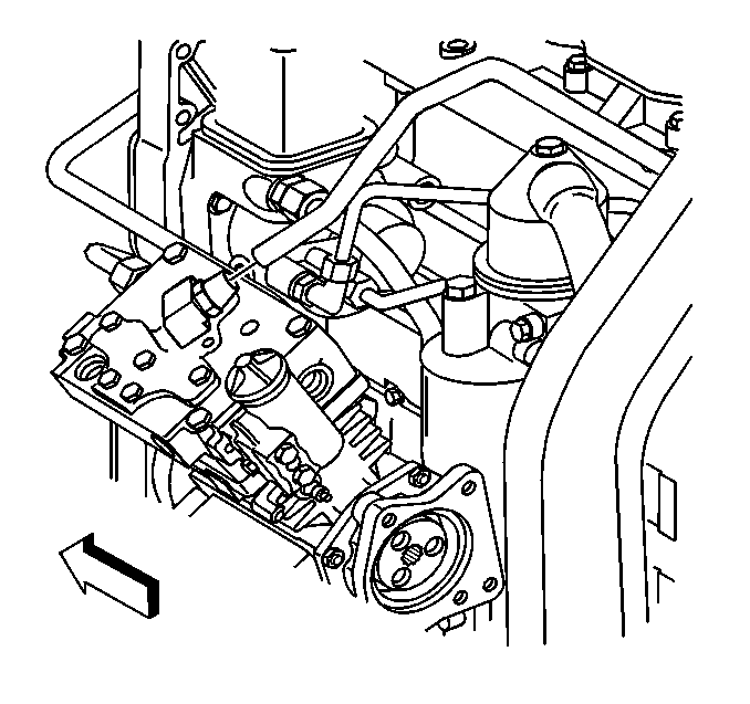
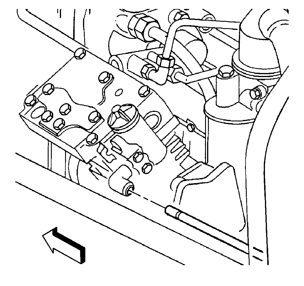
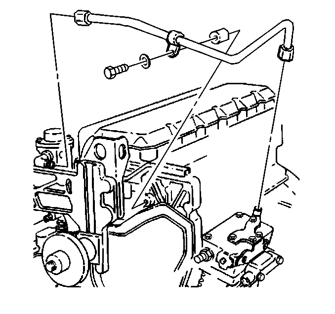
- Remove the nut and the air discharge line at the air compressor.
- Remove the governor air line at the air compressor. Refer to Air Compressor Governor Valve Replacement .
- Remove the air inlet hose.
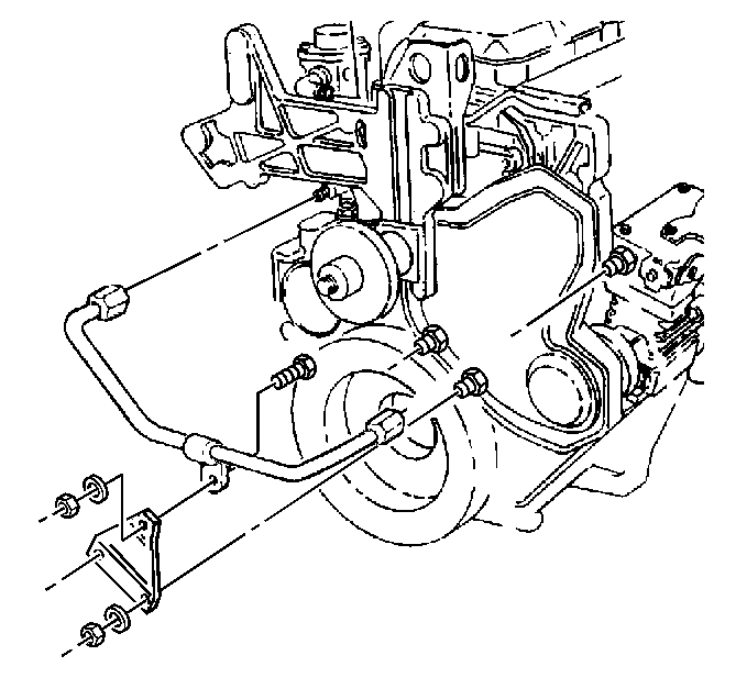
- Remove the coolant inlet hose at the air compressor.
- Remove the coolant outlet hose.
- Remove the oil supply hose and the clip at the air compressor.
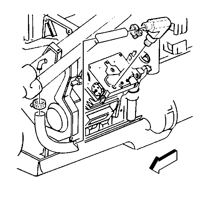
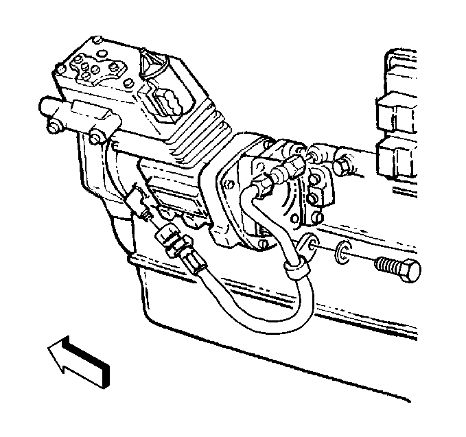
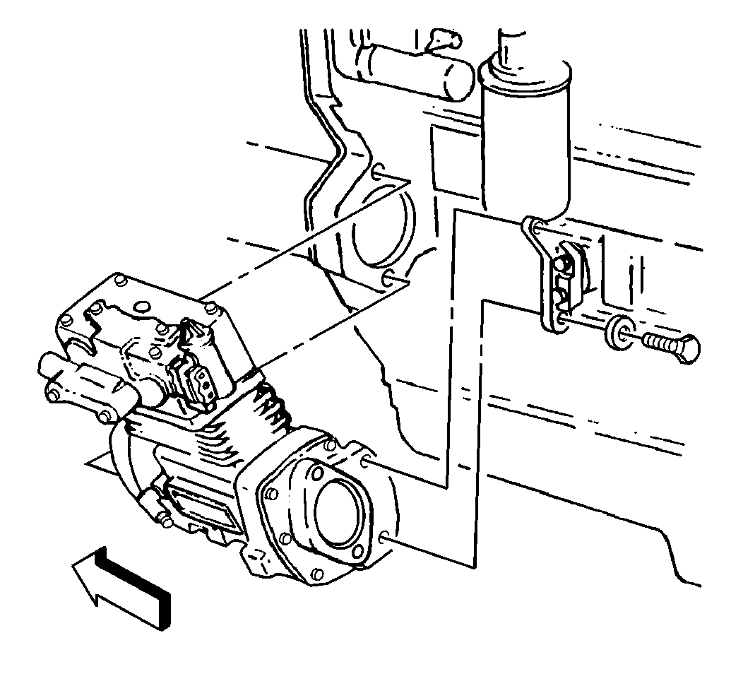
- Remove the power steering pump. Refer to Power Steering Pump Replacement in Power Steering System.
- Remove the air compressor flange mounting bolts and the washers.
- Remove the air compressor mounting bracket bolts and the washers.
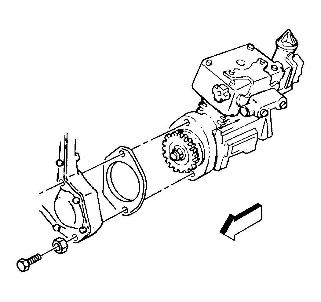
- Remove the air compressor.
- Remove the gasket from the air compressor.
- Clean the exterior of the air compressor.
- Inspect the air compressor crankcase for cracks or damage.
- Inspect the air compressor mounting flange for cracks or damage.
- Inspect the air compressor bracket for cracks or damage.
- Inspect the oil supply hose. Replace the oil supply hose if there is damage or leaking.
- Inspect the coolant inlet hoses. Replace the inlet coolant hoses if there is damage or leaking.
- Inspect the coolant outlet hoses. Replace the coolant outlet hoses if there is damage or leaking.
Installation Procedure
- Install the new air compressor flange gasket.
- Install the air compressor.
- Install the air compressor mounting flange washers and the bolts.
- Install the air compressor mounting bracket washers and the bolts.
- Finger tighten the air compressor mounting bracket bolts before torquing the bolts to specifications.
- Install the power steering pump. Refer to Power Steering Pump Replacement in Power Steering System.
- Install the oil supply hose.
- Install the coolant outlet hose at the air compressor.
- Install the coolant inlet line at the air compressor.
- Install the air inlet hose.
- Install the governor air line at the air compressor.
- Install the nut and the air discharge line at the air compressor.
- Fill the engine cooling system. Refer to Cooling System Draining and Filling in Engine Cooling.
- Fill the engine oil. Refer to Fluid and Lubricant Recommendations in General Information.
- Lower the cab. Refer to Cab Tilting in General Information.
- Check for any air leaks. Refer to Air Brake System Testing in Air Brakes.
- Check for proper brake operation.
- Remove the wheel blocks.
Notice: Use the correct fastener in the correct location. Replacement fasteners must be the correct part number for that application. Fasteners requiring replacement or fasteners requiring the use of thread locking compound or sealant are identified in the service procedure. Do not use paints, lubricants, or corrosion inhibitors on fasteners or fastener joint surfaces unless specified. These coatings affect fastener torque and joint clamping force and may damage the fastener. Use the correct tightening sequence and specifications when installing fasteners in order to avoid damage to parts and systems.
Tighten
Tighten the air compressor mounting flange bolts to 100 N·m
(74 lb ft).
Tighten
Tighten the air compressor mounting bracket bolts to 73 N·m
(54 lb ft).
Tighten
| • | Tighten the oil supply hose nut to 30 N·m (22 lb in). |
| • | Tighten the oil supply hose clip bolt to 67 N·m (49 lb ft). |
Tighten
Tighten the coolant outlet line eye bolt nut to 41 N·m
(30 lb ft).
Tighten
Tighten the coolant inlet line eye bolt to 41 N·m (30 lb ft).
Tighten
Tighten the air inlet hose clamp to 2.75 N·m (24 lb in).
Tighten
Tighten the air discharge line nut to 63 N·m (46 lb ft).
