Air Compressor Overhaul Disassembly/Assembly
Disassembly Procedure
Important: Before you disassemble the compressor, mark the following components
in order to show the relationships when you re-assemble the compressor:
• The cylinder head assembly to the cylinder body • The cylinder body to the crankcase
- Clean the compressor with engine degreaser.
- Remove the cylinder head bolts (1, 2, 8).
- Remove the cylinder head gaskets (3).
- Remove the air compressor cylinder body bolts (7).
- Remove the air compressor cylinder body (4).
- Remove the O-ring (5) from the cylinder body (4).
- Remove the two piston pin snap rings (2).
- Remove the piston pin (3).
- Remove the piston.
- Remove the piston ring assembly (4).
- Remove the crankshaft bearing cover bolts (6).
- Remove the O-ring (9) from the crankshaft bearing cover (3).
- Remove the front crankshaft bearing (1).
- Remove the connecting rod (3).
- Remove the connecting rod (3) from the crankshaft (2).
- Remove the crankshaft (2) and the rear crankshaft bearing (4).
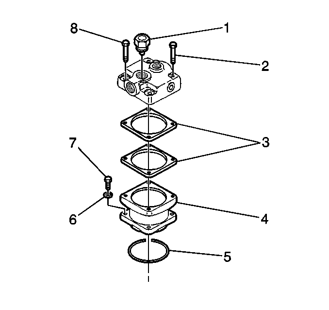
Tap the cylinder head with a soft faced mallet in order to break the gasket seal.
Use a wooden hammer in order to tap out the cylinder body from the crankcase.
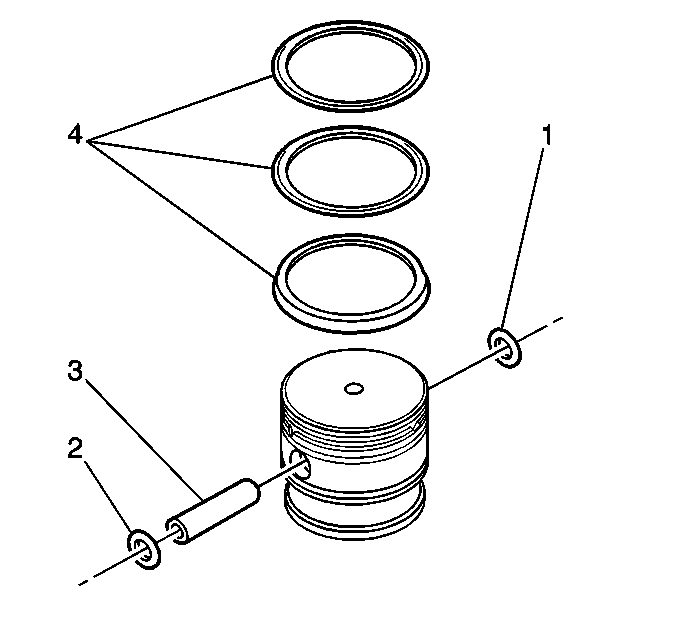
Important: Mark the relationship of the piston head to the connecting rod so that you can reassemble the parts later.
Use piston rings pliers in order to remove the piston ring.
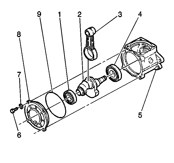
Use a suitable bearing remover in order to remove the crankshaft bearing.
Lower the connecting rod (3) by rotating the crankshaft (2).
Use a suitable press in order to remove the crankshaft bearing.
Assembly Procedure
Cleanliness during assembly is important. Dirt causes premature wear of the overhauled air compressor. Lightly lubricate all of the moving parts with clean engine oil during assembly. Engine oil provides an initial lubricant when you start the engine.
- Install the crankshaft rear bearing (4) onto the crankshaft.
- Install the crankshaft with the bearing into the crankcase (5).
- Install the connecting rod (3) onto the crankshaft (2).
- Install the crankshaft front bearing (1) onto the crankshaft (2).
- Install the O-ring (9) and the crankshaft bearing cover (8).
- Install the piston ring assembly (4).
- Install the first and the second rings with the R turned up.
- Set the piston rings to the following recommended positions:
- Install the piston pin (3) into the piston.
- Install the piston snap rings (2) into the piston.
- Install the cylinder body (4) and a new O-ring (5) into the crankcase.
- Install the new cylinder head gaskets (3) and a new cylinder head to the cylinder body.

Use a suitable press and a suitable support in order to assemble the crankshaft rear bearing.
Use a suitable press and a suitable sleeve in order to assemble the crankshaft front bearing.
Notice: Use the correct fastener in the correct location. Replacement fasteners must be the correct part number for that application. Fasteners requiring replacement or fasteners requiring the use of thread locking compound or sealant are identified in the service procedure. Do not use paints, lubricants, or corrosion inhibitors on fasteners or fastener joint surfaces unless specified. These coatings affect fastener torque and joint clamping force and may damage the fastener. Use the correct tightening sequence and specifications when installing fasteners in order to avoid damage to parts and systems.
Tighten
Tighten the crankshaft bearing cover bolts to 8 N·m (71 lb in).

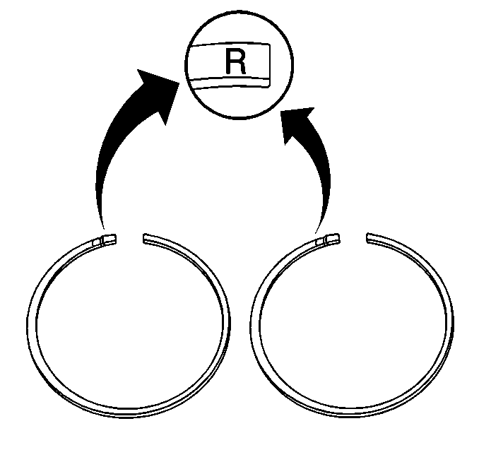
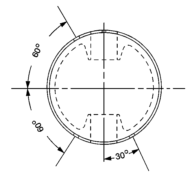
| 8.1. | Set the first compression ring at 30 degrees from the piston pin. |
| 8.2. | Set the second compression ring at 60 degrees clockwise of the center line that is perpendicular to the piston pin center line. |
| 8.3. | Set the expander ring at 60 degrees counter-clockwise of the center line that is perpendicular to the piston pin. |


Tighten
Tighten the bolts to 29 N·m (21 lb ft).
Tighten
Tighten the bolts to 49 N·m (36 lb ft).
Air Compressor Overhaul Cleaning and Inspection
Cleaning and Inspection
- Clean all of the parts in parts cleaner.
- Remove the carbon deposits from the discharge cavities.
- Remove the rust and the scale from the cooling cavities.
- Scrape any foreign matter from the body surfaces.
- Clean the oil passages with a wire.
- Inspect the crankcase surfaces for cracks and any other damage.
- Inspect the tapered ends of the crankshaft and all of the machined parts for the following:
- Inspect the cylinder bore for uneven wear.
- Inspect the piston for the following conditions:
- Complete the following measurements:
Dry the parts before you inspect the parts.
Use compressed air in order to remove dirt particles.
Use compressed air in order to blow the loosened foreign matter out of the oil passages.
| • | Wear |
| • | Scores |
| • | Damage |
| • | Scores |
| • | Cracks |
| • | Enlarged ring grooves |
| • | Replace the piston if necessary. |
| 10.1. | Measure the cylinder for uneven wear. The maximum limit is 0.1 mm (0.004 in). |
| 10.2. | Measure the piston and the cylinder clearance. The maximum limit is 0.2 mm (0.008 in). |
| 10.3. | Measure the piston ring groove and the piston ring clearance. The maximum limit is 0.15 mm (0.0059 in). |
| 10.4. | Measure the piston ring gap. The maximum limit is 1.0 mm (0.039 in). |
| 10.5. | Measure the piston pin and the piston hole clearance. The maximum limit is 0.1 mm (0.004 in). |
| 10.6. | Measure the piston pin and the connecting rod small end clearance. The maximum limit is 0.1 mm (0.004 in). |
| 10.7. | Measure the crankshaft journal and the connecting rod large end clearance. The maximum limit is 0.15 mm (0.0059 in). |
Air Compressor Overhaul Test After Overhaul
Important: Before you condemn or adjust the governor, check the dual air pressure gauge on the instrument panel. Use an accurate test gauge in order to verify the pressure that is shown on the dual air pressure gauge.
- Start the engine.
- Build up the air pressure.
- Observe the reading on the dual air pressure gauge on the instrument panel when the governor cuts out. Refer to Air Compressor Governor Valve Specifications for the cut-out pressure.
- While the engine is still running, slowly reduce the air pressure. Apply and release the brakes in order to reduce the air pressure.
- Observe the dual air pressure gauge when the governor cuts in. Refer to Air Compressor Governor Valve Specifications for the cut-in pressure.
- If you need to change the pressure settings, adjust the governor. Refer to Air Compressor Governor Valve Adjustment .
