Tools Required
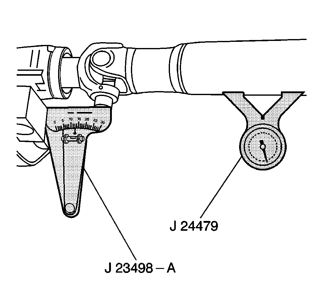
J 23498-A Inclinometer
Important:
• Correct driveline angles are necessary in order to prevent torsional
vibration. There must be at least a 1/2 degree working angle between
adjacent components of the propeller shaft in order to promote longer universal
joint life. • On some vehicles, adjustable auxiliary transmission mountings
are provided for adjusting the angle of the various driveline components. • On vehicles that do not have adjustable auxiliary transmission
mountings, use spacers or shims at the hanger bracket in order to achieve
proper adjustment of the angle of the driveline components.
Driveline Angles Inspection
Inspect the driveline angles when the vehicle is unloaded, and again when the vehicle is loaded. Ensure that the vehicle is in its normal operating position, with a full tank of fuel. Safely block the front wheels.
- Ensure that all of the parts are clean. The parts must be free of dirt or other foreign material in order to obtain an accurate measurement.
- Measure the tire air pressure in the tires. Ensure that the air pressures are at normal operating levels.
- Measure the ground surface for level. Take the measurements from both front to rear and from side to side.
- Place the J 23498-A on the rear propeller shaft bearing cap.
- Center the bubble in the sight glass, record the measurement. Ensure that the bearing cap is straight up and down.
- Rotate the propeller shaft 90 degrees. Place the J 23498-A on the front slip spline yoke bearing cap.
- Center the bubble on the sight glass, record the measurement. Ensure that the bearing cap is straight up and down.
- Place the J 23498-A on the rear propeller shaft bearing cap. Ensure that the bearing cap is straight up and down.
- Center the bubble in the sight glass, record the measurement.
- Rotate the propeller shaft 90 degrees. Place the J 23498-A on the front slip spline yoke bearing cap.
- Center the bubble on the sight glass, record the measurement.
- Subtract the smaller figure from the larger figure in order to obtain the rear universal joint angle.
- Place the J 23498-A on the front propeller shaft bearing cap.
- Center the bubble in the sight glass, record the measurement.
- Rotate the propeller shaft 90 degrees. Place the J 23498-A on the front slip spline yoke bearing cap.
- Center the bubble in the sight glass, record the measurement.
- Subtract the smaller figure from the larger figure in order to obtain the front universal joint angle.


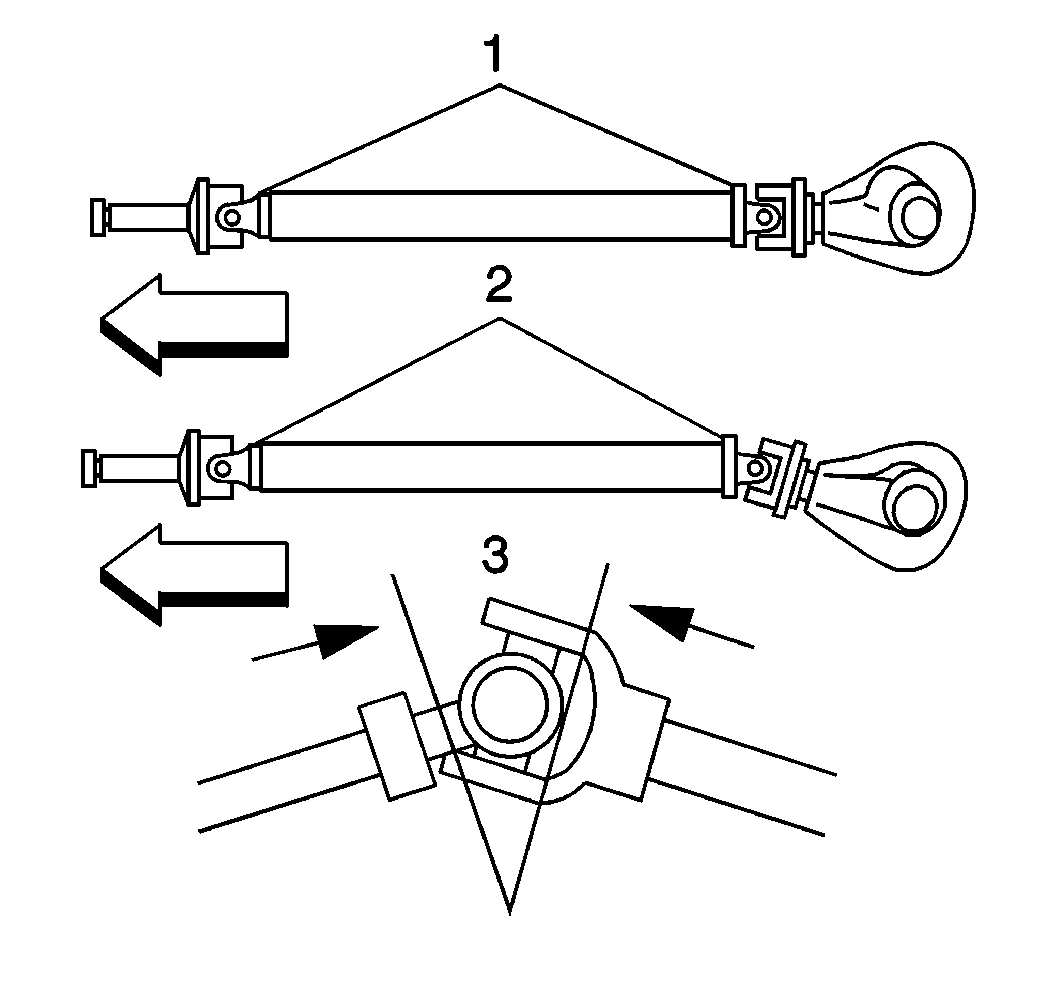
The recorded measurements determine if the journal cross operating angles of each propeller shaft set is more than 3 degrees. The working angles should not exceed 3 degrees (3). Ensure that the operating angle is greater than 1/2 degree in order to prevent brinelling of the bearing. If the propeller shaft speed equals 5,000 RPM, the maximum working angle cannot exceed 3.25 degrees and the minimum working angle equals 1/2 degree.
Auxiliary Transmission and Propeller Shaft Angle
Adjust the propeller shaft by raising or lowering the front or rear of the transmission using one of the following components:
| • | The adjustable mounting bolts |
| • | The adding or removing of shims |
| • | The plates |
| • | The washers |
Short-Coupled Universal Joints
Install the short coupled universal joints to the front and rear universal joints. Ensure that the angles do not exceed 3 degrees.
