Vehicle Control Module Diagnostic Procedures - Front Wheel Speed Sensor Inspection

| Subject: | NPR EFI Vehicle Control Module Diagnostic Procedures - Front Wheel Speed Sensor Inspection (Driveability and Emissions Manual Revision) |
| Models: | 1996-1997 NPR EFI models |
| Attention: | This Service Bulletin is intended for use by professional, qualified technicians. Attempting repairs or service without the appropriate training, tools, and equipment could cause injury to you or others and damage to your vehicle that may cause it not to operate properly. |
Service Information
The front wheel speed sensor inspection procedures contained in Section 3B - Vehicle Control Module System have been re-vised in the following Driveability and Emission Manual:
Manual | Page No. |
|---|---|
1996-1997 NPR/W4 (V8 Gasoline Engine) Publication No. FSE97-WSM-C01) | 3B-2, 153, 257, 258 |
This Service Bulletin contains the revised pages to the referenced Driveability and Emissions Manual (see RED marked areas on enclosed pages). Attach the enclosed pages to the referenced Driveability and Emissions Manual pages.
Driveability and Emissions (Gasoline) - Page 3B-2
DTC | Description | Page No. |
|---|---|---|
P0153 | Heated Oxygen Sensor (HO2S) Slow Response Bank 2, Sensor 1 | 3B-121 |
P0154 | Heated Oxygen Sensor (HO2S) Circuit Insufficient Activity Bank 2, Sensor 1 | 3B-123 |
P0155 | Heated Oxygen Sensor (HO2S) Heater Circuit Bank 2, Sensor 1 | 3B-126 |
P0157 | Heated Oxygen Sensor (HO2S) Circuit Low Voltage Bank 2, Sensor 2 | 3B-129 |
P0158 | Heated Oxygen Sensor (HO2S) Circuit High Voltage Bank 2, Sensor 2 | 3B-132 |
P0160 | Heated Oxygen Sensor (HO2S) Circuit Insufficient Activity Bank 2, Sensor 2 | 3B-135 |
P0161 | Heated Oxygen Sensor (HO2S) Heater Circuit Bank 2, Sensor 2 | 3B-138 |
P0171 | Fuel Trim System Lean Bank 1 | 3B-141 |
P0172 | Fuel Trim System Rich Bank 1 | 3B-144 |
P0174 | Fuel Trim System Lean Bank 2 | 3B-147 |
P0175 | Fuel Trim System Rich Bank 2 | 3B-150 |
P0300 | Engine Misfire Detected | 3B-153 |
P0301 | Cylinder 1 Misfire Detected | 3B-156 |
P0302 | Cylinder 2 Misfire Detected | 3B-159 |
P0303 | Cylinder 3 Misfire Detected | 3B-162 |
P0304 | Cylinder 4 Misfire Detected | 3B-165 |
P0305 | Cylinder 5 Misfire Detected | 3B-168 |
P0306 | Cylinder 6 Misfire Detected | 3B-171 |
P0307 | Cylinder 7 Misfire Detected | 3B-174 |
P0308 | Cylinder 8 Misfire Detected | 3B-177 |
P0325 | Knock Sensor (KS) Module Circuit | 3B-180 |
P0327 | Knock Sensor (KS) Circuit Low Voltage | 3B-183 |
P0336 | Crankshaft Position Sensor (CKP) Circuit Performance | 3B-187 |
P0337 | Crankshaft Position Sensor (CKP) Circuit Low Frequency | 3B-190 |
P0338 | Crankshaft Position Sensor (CKP) Circuit High Frequency | 3B-193 |
P0339 | Crankshaft Position Sensor (CKP) Circuit Intermittent | 3B-196 |
P0340 | Camshaft Position Sensor (CMP) Circuit Performance | 3B-199 |
P0341 | Camshaft Position Sensor (CMP) Circuit | 3B-202 |
P0401 | Exhaust Gas Recirculation (EGR) System | 3B-204 |
P0441 | Evaporative Emission (EVAP) System No Flow During Purge | 3B-207 |
P0500 | Vehicle Speed Sensor (VSS) Circuit | 3B-210 |
P0506 | Idle System Low - Idle Air Control (IAC) Responding | 3B-213 |
P0507 | Idle System High - Idle Air Control (IAC) Responding | 3B-215 |
P1106 | Manifold Absolute Pressure (MAP) Sensor Circuit Intermittent High Voltage | 3B-217 |
P1107 | Manifold Absolute Pressure (MAP) Sensor Circuit Intermittent Low Voltage | 3B-220 |
P1111 | Intake Air Temperature (IAT) Sensor Circuit Intermittent High Voltage | 3B-223 |
P1112 | Intake Air Temperature (IAT) Sensor Circuit Intermittent Low Voltage | 3B-226 |
P1114 | Engine Coolant Temperature (ECT) Sensor Circuit Intermittent Low Voltage | 3B-228 |
P1115 | Engine Coolant Temperature (ECT) Sensor Circuit Intermittent High Voltage | 3B-230 |
P1121 | Throttle Position (TP) Sensor Circuit Intermittent High Voltage | 3B-233 |
P1122 | Throttle Position (TP) Sensor Circuit Intermittent Low Voltage | 3B-235 |
P1133 | Heated Oxygen Sensor (HO2S) Insufficient Switching Bank 1, Sensor 1 | 3B-237 |
P1134 | Heated Oxygen Sensor (HO2S) Transition Time Ratio Bank 1, Sensor 1 | 3B-240 |
P1153 | Heated Oxygen Sensor (HO2S) Insufficient Switching Bank 2, Sensor 1 | 3B-242 |
P1154 | Heated Oxygen Sensor (HO2S) Transition Time Ratio Bank 2, Sensor 1 | 3B-245 |
P1345 | Crankshaft Position/Camshaft Position (CKP/CMP) Correlation | 3B-247 |
P1351 | Ignition Control (IC) Circuit High Voltage | 3B-249 |
P1361 | Ignition Control (IC) Circuit Low Voltage | 3B-252 |
P1380 | Rough Road Data Unusable | 3B-255 |
Inspection Procedure for Wheel Speed Sensor | 3B-257 | |
P1381 | Misfire Detected VCM Serial Data | 3B-258 |
P1406 | Exhaust Gas Recirculation (EGR) Valve Pintle Position Circuit | 3B-259 |
P1441 | Evaporative Emission (EVAP) System Flow During Non-Purge | 3B-263 |
P1508 | Idle Air Control (IAC) System Low RPM | 3B-266 |
P1509 | Idle Air Control (IAC) System High RPM | 3B-269 |
VCM Wiring Diagrams | 3B-272 | |
On-Vehicle Service | 3B-288 | |
Vehicle Control Module | 3B-288 | |
VCM Replacement with PROM | 3B-288 | |
DTC P0300 - Engine Misfire Detected - Page 3B-153

CIRCUIT DESCRIPTION
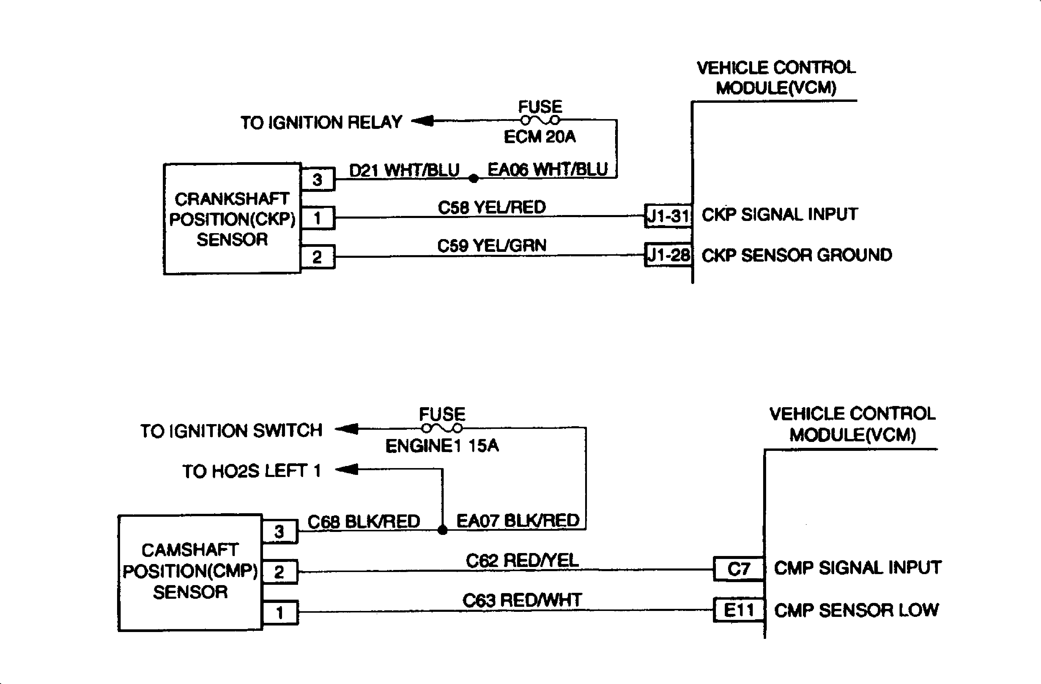
Misfire is detected using the crankshaft position sensor and camshaft position sensor. The speed of the crankshaft is monitored by the VCM which has the ability to detect deceleration of the crankshaft that are not associated with normal engine speed reduction. To determine if a misfire occurred, the deceleration information is compared to engine speed and engine load. If a misfire event is determined, the crankshaft position is compared to the cam sensor signal in order to determine which cylinder misfired. This information will be stored in separate accumulators for each cylinder. Upon completion (or failure) of the test, the VCM will evaluate the number of misfires in each accumulators, If me accumulators are somewhat even or if three or more cylinders are misfiring, then this determines that a random misfire has occurred. The VCM also utilizes input from the ABS wheel speed sensor in order to determine if a rough road condition exists which could cause crankshaft acceleration and deceleration. If a rough road condition exists, the diagnostic will not run. DTC P0300 is a type "B" DTC.
CONDITIONS FOR SETTING THE DTC
| • | No TP sensor DTCs |
| • | No MAF sensor DTCs |
| • | No IC control DTCs |
| • | No VS sensor DTCs |
| • | No Crankshaft Position sensor DTCs |
| • | Rough Road is not detected |
| • | ECT is between -.75°C and 95.2°C |
| • | Engine Speed between 300 RPM and 5600 RPM |
| • | System voltage between 9V and 16V |
| • | + Throttle position change is less than 4.9% for 100 msec |
| • | - Throttle position change is less than 2.9% for 100 msec |
| • | Misfire is detected |
ACTION TAKEN WHEN THE DTC SETS
If the VCM determines that the misfire is significant enough to have a negative impact on emissions, the MIL will be turned "ON" after the misfire has been detected on two non consecutive trips under the same operating conditions. If the misfire is severe enough that catalytic converter damage could result, the MIL will flash while the misfire is present.
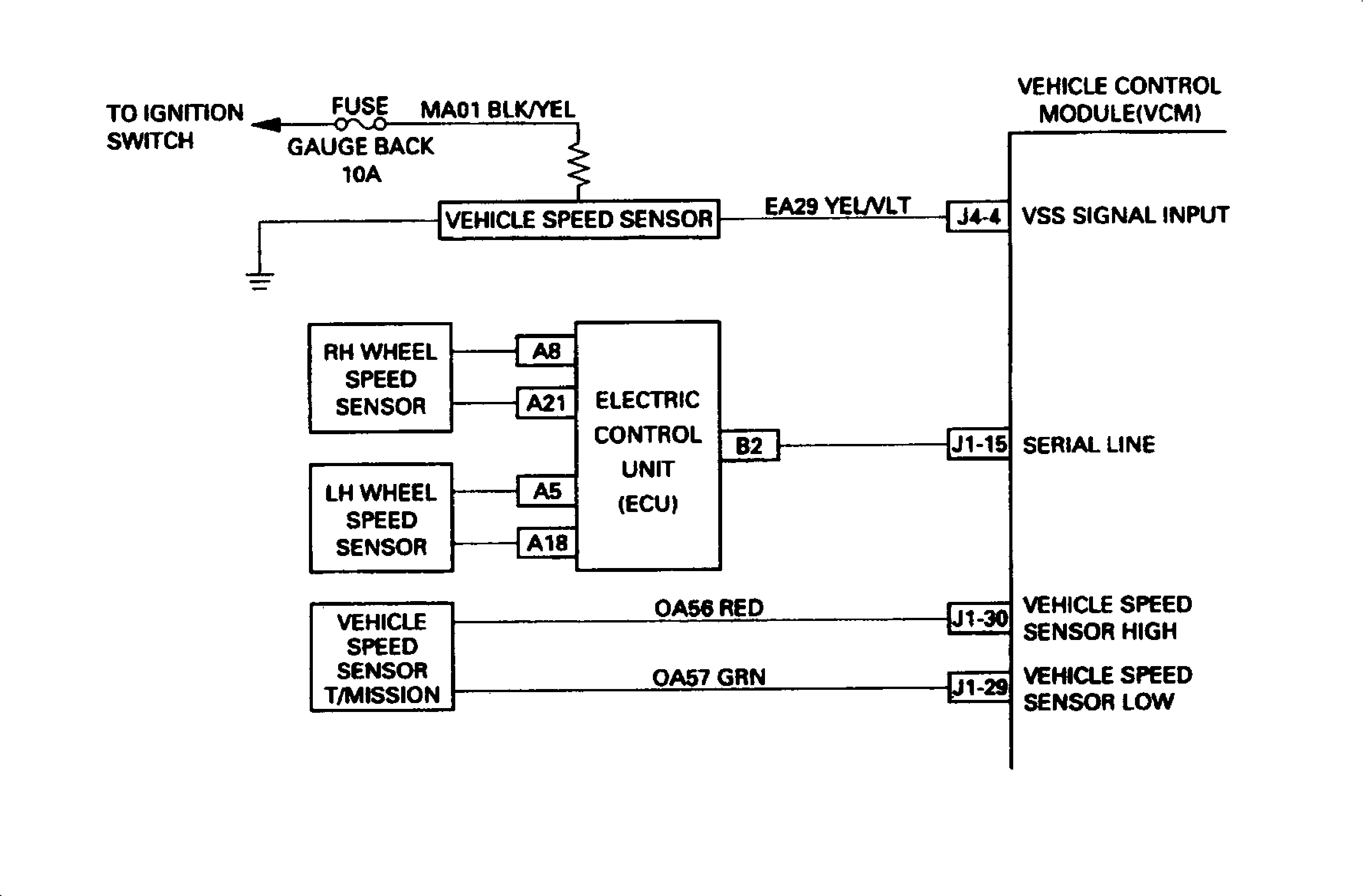
When the DTC is set, be sure to check to see if Front Wheel Speed Sensor is opened or shorted.
In case an abnormality is found in the sensor, it may possibly be a case of erroneous detection during a rough road run. The Wheel Speed Sensor Diagnosis is as attached.
CONDITIONS FOR CLEARING me MIL/DTC
The VCM will turn the MIL "OFF" after three consecutive trips without a fault condition present A history DTC will be cleared if no fault conditions have been detected for forty warm-up cycles (coolant temperature has risen 40°F from start-up coolant temperature and engine coolant temperature exceeds 160°F mat same ignition cycle) or the scan tool clearing has been used.
Inspection Procedure for Wheel Speed Sensor - Page 3B-257

- Disconnect the connector J1-15 from Vehicle Control Module (V.C.M.).
- Inspect open circuit between connector pin A8 and A21 for right front wheel speed sensor and between connector pin A5 and A18 for left front wheel speed sensor.
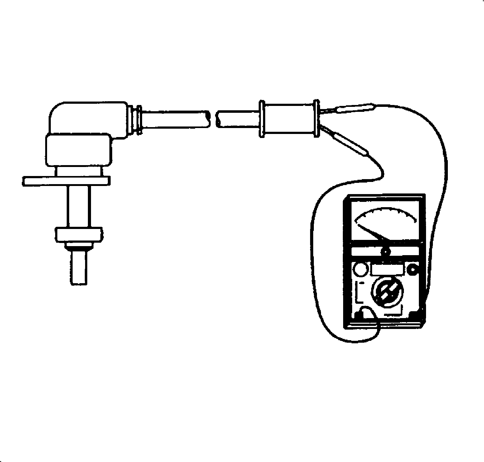
- Measure the resistance of wheel speed sensor.
- If it is made opened circuit or the wheel speed sensor resistance is without standard value, replace the wheel speed sensor.

Specifications
Standard Resistance = 18k ohms +/- 0.18 k ohms
DTC P1381 - Misfire Detected VCM Serial Data - Page 3B-258
Step | Action | Values | Yes | No |
|---|---|---|---|---|
1 |
Important: Before clearing DTC(s) use the scan tool to record Freeze Frame and Failure Records for reference, as data will be lost when the "Clear Info" function is used. Was the "On-Board Diagnostic (OBD) System Check" performed? | -- | Go to Step 2 | Go to OBD System Check |
2 |
Was a problem found? | -- | Go to Step 3 | -- |
3 | Repair as necessary. Is the action complete? | -- | Go to Step 4 | -- |
4 |
Does the scan tool indicate that this diagnostic Ran and Passed? | -- | Go to Step 5 | -- |
5 | Using the scan tool, select "Capture Info", "Review Info." Are any additional DTCs displayed that have not been diagnosed? | -- | Go to Applicable DTC Table | System OK |
