Crankshaft and Bearing Installation Bearing Installation
- Apply engine oil to the main bearing inserts.
- Install the upper main bearing inserts.
- Install the crankshaft.
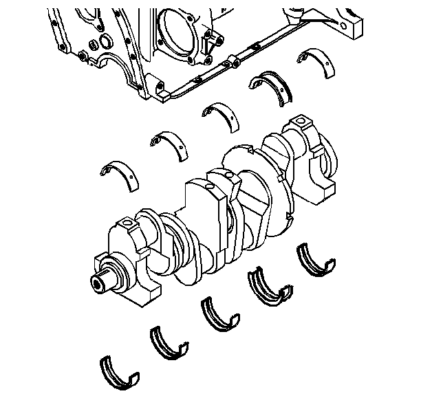
- Install the lower main bearing inserts to the main bearing caps.
| • | Make sure that the inserts are the correct size. |
| • | Apply engine oil to the inserts. |
- Measure the main bearing clearance. Refer to Engine Mechanical
Specifications.
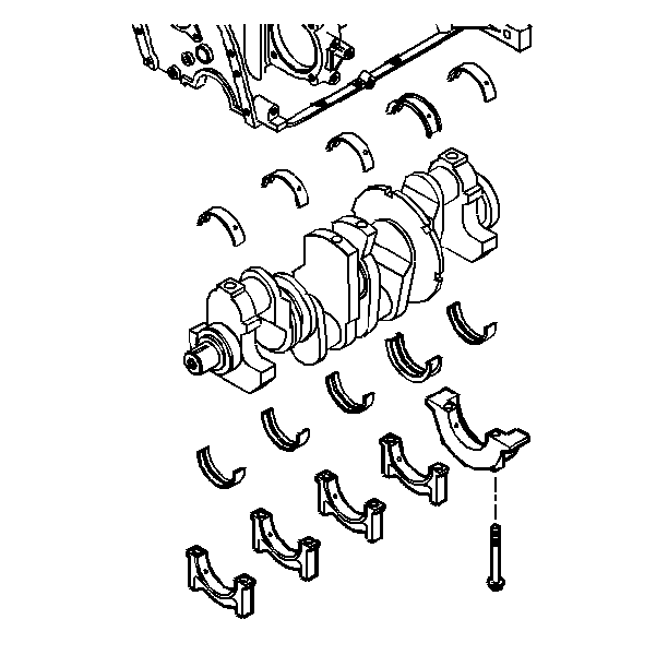
- Install the main bearing caps to the engine block.
- Install the main bearing cap bolts to the engine block.
Tighten
Tighten the main bearing cap bolts first to 50 N·m (37 lb ft).
Notice: Use the correct fastener in the correct location. Replacement fasteners
must be the correct part number for that application. Fasteners requiring
replacement or fasteners requiring the use of thread locking compound or sealant
are identified in the service procedure. Do not use paints, lubricants, or
corrosion inhibitors on fasteners or fastener joint surfaces unless specified.
These coatings affect fastener torque and joint clamping force and may damage
the fastener. Use the correct tightening sequence and specifications when
installing fasteners in order to avoid damage to parts and systems.
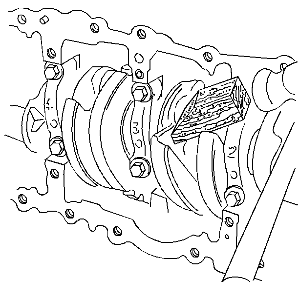
- Measure the crankshaft end play using
the following procedure:
| 8.1. | Firmly thrust the crankshaft rearward. |
| 8.2. | Firmly thrust the crankshaft forward. |
| 8.3. | This will align the main bearing and the crankshaft thrust surfaces. |
Tighten
Tighten the main bearing cap bolts to 95 N·m (70 lb ft).
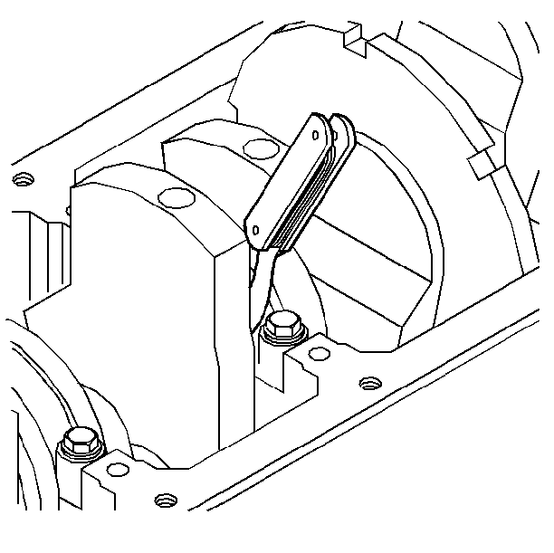
- Measure the crankshaft end play at the front end of the rear main bearing
with a feeler gauge.
| • | The crankshaft should still be wedged forward. |
| • | The proper clearance is 0.0511-0.1780 mm (0.002-0.007 in). |
- Install the oil pump. Refer to Oil Pump Installation.
- Install the oil pan. Refer to Oil Pan Installation.
Crankshaft and Bearing Installation Bearing Fitting
Important: Bearing failure, other than normal wear must be investigated carefully.
- Inspect the crankshaft journals for the following conditions:
| • | Shiny areas indicating high areas on journal surfaces |
- Inspect the connecting rod and crankshaft bearing bores for the
following conditions:
| • | An out-of-round condition in the bearing bores |
| • | Burrs or blockage of oil holes |
Important: Do not mix bearing inserts of different nominal size. It is important
to remember that some engines are assembled with undersize bearing inserts
during the manufacturing process. Equivalent undersize service bearings are
available. Measure the clearance of all bearings, this is especially important
if an original equipment bearing is being replaced with a new one.
- Install the bearing inserts
- Measure the bearing clearance. To determine the correct replacement
insert size, the bearing clearance must be measured accurately. Either of
the following two methods may be used, however, method A gives more reliable
results and is preferred.
- Method A yields measurements from which the bearing clearance
can be computed. Method B yields the bearing clearance directly. Method B
does not give any indication of bearing journal runout.
Method A
- Measure the crankshaft journal diameter with a micrometer in several
places, approximately 90 degrees apart, and average the measurements.
- Measure the taper and runout
- Measure the bearing insert I.D. with an inside micrometer. Measure
at 90 degrees to the split line of the bearing.
- Compare the measurements to the specifications.
- If the measurements are not within specifications, repair or replace
parts as needed to correct the condition.
Method B
- Clean and install the bearing inserts, and the crankshaft into
the block.
- Place a piece of gaging plastic across the entire bearing width.
- Seat the bearing cap carefully by tapping it lightly with a suitable
tool.
Notice: To prevent the possibility of cylinder block and/or main bearing cap
damage, tap the main bearing caps into the cylinder block cavity with a brass
or leather mallet before installing the attaching bolts. Do not use the attaching
bolts to pull the caps into their seats.
- Tighten the bearing cap bolts to specification.
Important: Do not rotate the crankshaft.
- Remove the bearing cap, leaving the gaging plastic in place. It does
not matter whether the gaging plastic adheres to the journal or to the bearing
cap.
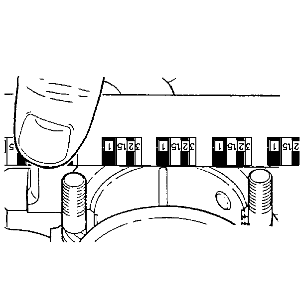
- Measure the flattened gaging plastic at the widest point.
- Remove all traces of the gaging plastic after measuring.


