Fuel System Operation
The SFI system consists of the following parts:
| • | The fuel supply system (fuel tank, pump, pipes) |
| • | The fuel pump electrical circuit |
| • | Intake manifold assembly, including the following items: |
| - | The lower manifold assembly, including the following items: |
| • | The fuel pressure regulator assembly |
| - | The upper manifold assembly, including the following items: |
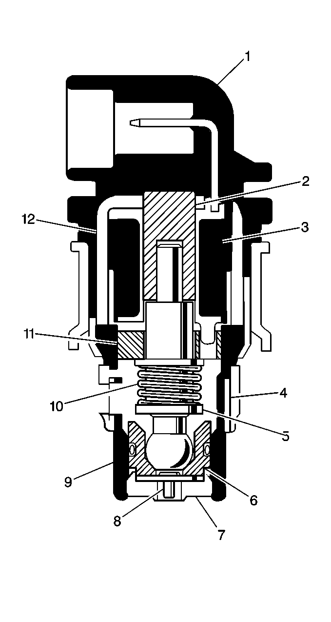
| • | The Idle Air Control (IAC) valve |
| • | The Throttle Position (TP) sensor |
Fuel Pump Electrical Circuit
When the ignition switch is turned to the ON position, the PCM energizes
the fuel pump relay for 2 seconds allowing the fuel pump to pressurize the
fuel system. If the PCM does not receive any ignition reference pulses,
engine cranking or running, within 2 seconds, the PCM de-energizes
the fuel pump relay, this causes the fuel pump to stop.
An inoperative fuel pump relay will cause no start.
Accelerator Controls
The accelerator control system is a cable type and there are no linkage
adjustments. Therefore, the only specific cable for each application must
be used. When work has been performed on the accelerator controls, always
make sure that all components are installed correctly and that the linkage
and cables are not rubbing or binding in any manner. The throttle should
operate freely without binding between full closed and wide open throttle
(WOT).
Intake Manifold Assembly (Upper and Lower Manifold Assemblies)

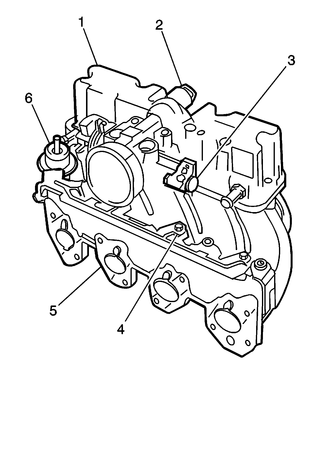
The intake manifold is made up of the upper (1) and lower (5) manifold
assemblies.
The upper manifold assembly is a single casting which includes the following
items:
| • | The upper portion of the air chamber (plenum) |
| • | The air inlet (fitted with a throttle valve) |
This assembly replaces the individual throttle body assembly and plenum
components.
The throttle valve controls the air flow into the engine, thereby, controlling
engine output. The driver opens the throttle valve through the accelerator
controls. During engine idle, the throttle valve is almost closed. The air
flow control is handled by the Idle Air Control (IAC) valve (2). Various components
generate the vacuum signals needed.
The nonadjustable, throttle shaft-driven, Throttle Position (TP) sensor
(3) is attached to the upper manifold assembly opposite the throttle cam lever.
The lower manifold is a single casting that includes the intake runners
and a longitudinal fuel passage with intersecting injector bores in each runner.
This assembly replaces the individual fuel rail and the manifold components
used in other systems. The information on the fuel injectors (4) and the pressure
regulator (6) are covered separately.
Bottom Feed Type, Sequential Fuel Injectors


