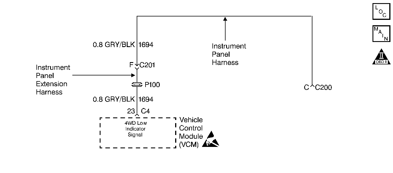
Circuit Description
Although 4WD is not applicable to the GMT150, a 4WD low circuit exists
as part of the instrument panel extension harness and instrument panel harness.
Circuit 1694 extends from VCM terminal C4-23 to the instrument panel
harness connector (terminal C). This circuit has the potential, if grounded,
to set a DTC P1875. Even though the possibility of this occurring is very
remote, a diagnostic check must be included in the event this DTC sets.
When the VCM detects a continuous short to ground in the 4WD low circuit,
then DTC P1875 sets. DTC P1875 is a type A DTC.
Conditions for Setting the DTC
| • | No TP DTCs P0121, P0122 or P0123. |
| • | No VSS Assy. DTC P0502. |
| • | No TCC Sol. Valve DTC P0740. |
| • | No TCC Stuck ON DTC P0742. |
| • | No 1-2 SS Valve DTC P0751 or P0753. |
| • | No 2-3 SS Valve DTC P0756 or P0758. |
| • | No TFP Val. Position Sw. DTC P1810. |
| • | No TCC PWM Sol. Valve DTC P1860. |
| • | The engine speed is greater than 450 RPM for 8 seconds. |
| • | The vehicle speed is greater than 11 km/h (7 mph). |
| • | The TP angle is 17-50%. |
| • | The engine torque is between 50-400 lb ft. |
| • | The engine vacuum is between 0-105 kPa. |
| • | The shift solenoid performance counters are zero. |
| • | The TFT is 20-120°C (68-248°F). |
| • | All of the above conditions are met and the following fail condition
occurs: |
| - | Four-wheel drive low is stuck ON (circuit 1694 is grounded) for
5 seconds. The TCC slip speed is -3000 to -50 RPM.
The speed ratio is 0.8-1.2. (The speed ratio is the engine speed divided
by transmission output speed). |
Action Taken When the DTC Sets
| • | The VCM illuminates the Malfunction Indicator Lamp (MIL). |
Conditions for Clearing the MIL/DTC
| • | The VCM turns OFF the MIL after three consecutive ignition cycles
without a failure reported. |
| • | A scan tool can clear the DTC from the VCM history.
The VCM clears the DTC from the VCM history if the vehicle completes 40 warm-up
cycles without a failure reported. |
| • | The VCM cancels the DTC default actions when the fault no longer
exists and the ignition is OFF long enough in order to power down the VCM. |
Diagnostic Aids
| • | Inspect the wiring for poor electrical connections at the VCM.
Look for the following conditions: |
| - | A broken wire inside the insulation |
| • | When diagnosing for an intermittent short condition, massage the
wiring harness while watching the test equipment for a change. |
Test Description
The numbers below refer to the step numbers on the diagnostic chart.
-
This step tests for a short to ground in
circuit 1694.
DTC P1875 Four-Wheel Drive Low Circuit Malfunction
Step
| Action
| Value(s)
| Yes
| No
|
1
| Was the Powertrain On-Board Diagnostic (OBD) System Check performed?
| --
|
Go to Step 2
| Go to OBD System Check
|
2
|
- Install the scan tool.
- With the engine OFF, turn the ignition switch to the RUN position.
Important: Before clearing the DTCs, use the scan tool in order to record the Freeze
Frame and Failure Records for reference. The Clear Info function will erase
the data.
- Record the DTC Freeze Frame and Failure Records, then clear the DTC.
- Turn the ignition switch OFF.
- Disconnect the C4 (black) VCM connector.
- Using the J 39200
DVOM and J 35616-A
Connector Test Adapter Kit, measure
the resistance between C4-23 and a known good ground.
Is the resistance measured less than the specified value?
| 1000 ohms
|
Go to Step 3
| Go to Diagnostic Aids
|
3
| Inspect circuit 1694 for a short to ground. Repair the circuit if necessary.
Refer to Electrical Diagnosis, Section 8A.
Did you find and correct a problem?
| --
|
Go to Step 5
|
Go to Step 4
|
4
| Replace
the VCM. Refer to VCM Replacement, Section 6.
Is the replacement complete?
| --
|
Go to Step 5
| --
|
5
| In order to verify your repair, perform the following procedure:
- Select DTC.
- Select Clear Info.
- Drive the vehicle in 4th gear with the TCC on. The speed ratio
must be 0.8-1.2 for 5 seconds.
- Select Specific DTC. Enter DTC P1875.
Has the test run and passed?
| --
| System
OK
| Begin the diagnosis
again. Go to Step 1
|

