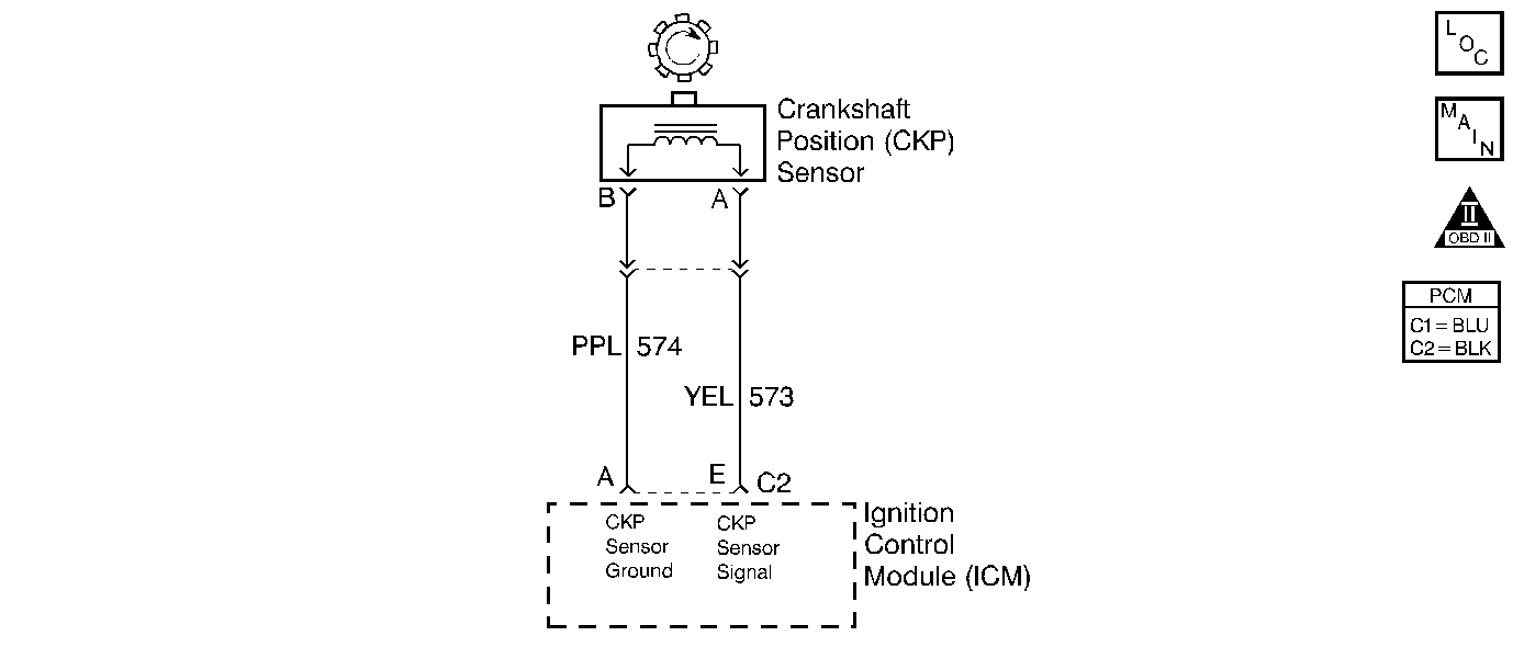
Circuit Description
The electronic ignition control module (ICM) sends a reference signal to the powertrain control module (PCM) seven times per crankshaft revolution to indicate crankshaft position and RPM so that the PCM can determine when to pulse the ignition coils and control the ignition timing. This signal is called medium resolution, 7X reference, because it occurs seven times per crankshaft revolution. The ICM applies 5 volts through the 7X reference circuit and, in effect, switches this circuit to ground for a very short period of time. The seventh pulse is the sync pulse and is used for crankshaft position reference.
Conditions for Setting the DTC
The CKP resync counter goes more than 15 within 4 minutes and 15 seconds.
Conditions for Setting the DTC
The CKP resync counter goes more than 15 within 4 minutes and 15 seconds.
Action Taken When the DTC Sets
| • | The malfunction indicator lamp (MIL) will illuminate after two consecutive ignition cycles in which the diagnostic runs with the malfunction present. |
| • | The PCM will record the operating conditions at the time that the diagnostic fails. The Freeze Frame and Failure Records buffers will store this information. |
| • | A history DTC stores. |
Conditions for Clearing the MIL/DTC
| • | The malfunction indicator lamp (MIL) will turn OFF after 3 consecutive ignition cycles in which the diagnostic runs without a fault. |
| • | A history DTC will clear after 40 consecutive warm up cycles without a fault. |
| • | Use a scan tool to clear the DTCs. |
Diagnostic Aids
| • | If the complaint was Cranks But Will Not Run, the DTC P0335 may set when attempting to start the engine more than 15 times and the ignition is not turned OFF between the attempts. |
| • | A rubbed through wire insulation or a poor connection may cause an intermittent problem. |
| • | A defective reluctor wheel can result in an intermittent. Remove the crankshaft sensor and inspect the reflector wheel through the hole. Check the porosity and condition of the wheel. |
Test Description
The number(s) below refer(s) to the step number(s) on the Diagnostic Table.
-
The Powertrain OBD System Check prompts you to complete some of the basic checks and to store the freeze frame and failure records data on the scan tool if applicable. This creates an electronic copy of the data captured when the malfunction occurred. The scan tool stores this data for later reference.
-
This step determines if the PCM recognizes a problem. If the DTC does not reset at this point, the problem may be intermittent.
-
When a Medium Resolution Resync occurs, engine stumble should also occur. If a component electrical connection or an electrical wire is malfunctioning, an engine stumble or a medium resolution resync may be induced by wiggling the circuit or electrical connector.
-
Operating malfunctioning non-engine related electronic components may emit Electromagnetic Interference (EMI) which may cause a resync. This step will determine if the medium resolution resync(s) are being caused by an outside source.
-
Thoroughly check any suspected circuitry for the following conditions:
-
An intermittent problem may be caused by the following conditions:
-
Program the replacement PCM and perform the crankshaft position system variation learn procedure. Refer to the latest Isuzu Technical Communications System (ITCS) procedure for PCM reprogramming and also refer to the Crankshaft Position System Variation Learn for the Crankshaft Position System Variation Learn Procedure.
| • | Backed out terminals |
| • | Improper mating |
| • | Broken locks |
| • | Improperly formed or damaged terminals |
| • | Poor terminal to wiring connections |
| • | Physical damage to the wiring harness |
| • | Rubbed through wire insulation |
| • | Poor electrical connection |
| • | Broken wire in the insulation |
Step | Action | Value(s) | Yes | No | ||||||
|---|---|---|---|---|---|---|---|---|---|---|
Did you perform the Powertrain On-Board Diagnostic (OBD) System Check? | -- | |||||||||
2 | Attempt to start the engine. Will the engine start? | -- | ||||||||
Did the MIL illuminate? | 5 | |||||||||
|
Caution: Avoid contact with moving parts and hot surfaces while working around a running engine in order to prevent physical injury. With the engine is running, wiggle the electrical connectors of the following components and related circuits, while listening for the engine to stumble:
Does the engine stumble? | -- | |||||||||
Does the Med. Resolution Resync Counter on the scan tool increment while operating any non-engine related electronic components? | -- | |||||||||
Is the action complete? | -- | -- | ||||||||
7 | Did the MIL illuminate in step 3? | -- | ||||||||
Was a repair necessary? | -- | |||||||||
9 |
Is the action complete? | -- | -- | |||||||
10 |
Did the MIL illuminate? | 5 | ||||||||
11 |
Did the MIL illuminate? | 5 | ||||||||
Did the MIL illuminate? | 5 | Go to Diagnostic Aids | ||||||||
13 |
Does the scan tool indicate that this diagnostic has ran and passed? | -- | ||||||||
14 | Check to see if any additional DTCs are set. Does the scan tool display any DTCs that you have not diagnosed? | -- | Go to applicable DTC table | System OK |
