GM Service Manual Online
For 1990-2009 cars only

Removal Procedure

  1. Disconnect the battery negative cable. Refer to Battery Replacement in Engine Electrical.
  2. Remove the hood. Refer to Hood Replacement in Body Front End.
  3. If the vehicle is equipped with a manual transmission, remove the shift lever. Refer to Shift Lever in Manual Transmission - NV 1500.
  4. Raise the vehicle. Refer to Lifting and Jacking the Vehicle in General Information.
  5. Disconnect the exhaust pipe from the exhaust manifold. Refer to Exhaust Manifold Pipe Replacement in Engine Exhaust.
  6. Disconnect the catalytic converter from the exhaust pipe. Refer to Catalytic Converter Replacement in Engine Exhaust.

  7. Object Number: 354503  Size: SH
  8. Remove the oil filter drain deflector from the brace rod, if equipped.

  9. Object Number: 33772  Size: SH
  10. Remove the brace rods from the engine and the transmission, manual transmission only.
  11. Remove the starter motor. Refer to Starter Motor Replacement in Engine Electrical.
  12. In order to gain access to the top transmission bolts, lower the rear of the transmission after removing the crossmember. The engine and transmission will pivot on the engine mounts.
  13. Remove the transmission.
  14. • Refer to Transmission Replacement in Manual Transmission - NV 1500.
    • Refer to Transmission Replacement in Automatic Transmission - 4L60-E.
  15. Disconnect the oxygen sensor electrical connector. Refer to Oxygen Sensor Replacement in Engine Controls.

  16. Object Number: 43037  Size: SH
  17. Remove the right fender wheelhouse extension. Refer to Wheelhouse Extension Replacement in Body Front End.
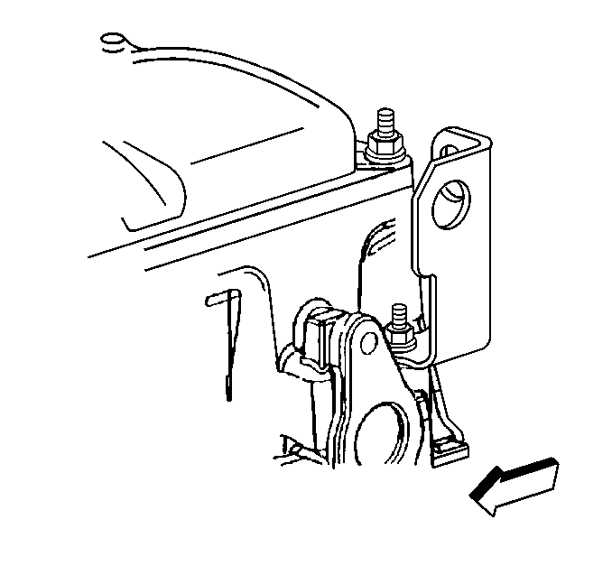
  18. Remove the generator rear brace using the following procedure:
  19. 14.1. Remove the bolt from the rear of the generator.
    14.2. Remove two nuts holding the brace to the engine.
    14.3. Remove the brace from the engine.

    Object Number: 354620  Size: SH
  20. Remove the bolt holding the battery negative cable to the engine.
  21. Remove the bolt holding the ground wires to the engine.
  22. Disconnect the following electrical connectors from the left side of the engine:
  23. • Engine oil pressure gauge sensor
    • Camshaft position (CMP) sensor
    • Ignition control module (ICM)
    • EVAP purge canister solenoid valve
    • Crankshaft position (CKP) sensor
    • Knock (KS) sensor

    Object Number: 354625  Size: SH
  24. Remove the nut holding the engine wiring harness bracket to the rear lower intake stud.
  25. Remove the bolt holding the engine wiring harness to the intake manifold.
  26. Lower the vehicle.
  27. Remove the air intake duct. Refer to Air Cleaner Inlet Duct Replacement in Engine Controls.
  28. Remove the radiator. Refer to Radiator Replacement in Engine Cooling.
  29. Remove the drive belt. Refer to Drive Belt Replacement .
  30. Important: Do not evacuate the A/C system.

  31. Remove the air conditioning compressor, if equipped, and set it aside. Refer to Air Conditioning Compressor Replacement in HVAC Systems with A/C - Manual.
  32. Remove the power steering pump and set it aside. Refer to Power Steering Pump Replacement in Power Steering Systems.
  33. Disconnect both heater hoses from the heater core. Refer to Heater Hoses Replacement in Heating and Ventilation (Non-A/C).

  34. Object Number: 346145  Size: SH
  35. Disconnect the vacuum brake booster hose.
  36. Caution: In order to avoid possible injury or vehicle damage, always replace the accelerator control cable with a NEW cable whenever you remove the engine from the vehicle.

    In order to avoid cruise control cable damage, position the cable out of the way while you remove or install the engine. Do not pry or lean against the cruise control cable and do not kink the cable. You must replace a damaged cable.

  37. Disconnect the accelerator control cable and the cruise control cable, if equipped.
  38. • Refer to Accelerator Control Cable Replacement in Engine Controls.
    • Refer to Cruise Control Cable Replacement in Cruise Control.

    Object Number: 5659  Size: SH
  39. Disconnect the battery positive cable from the battery.
  40. Disconnect the 12 volt supply from the mega fuse.
  41. Leave the battery positive cable on the engine.

  42. Disconnect the following electrical connectors from the top of the engine:
  43. • Fuel injector harness
    • Engine coolant temperature (ECT) sensor
    • Idle air control (IAC) motor
    • Manifold absolute pressure (MAP) sensor
    • Throttle position (TP) sensor
  44. Disconnect the engine block heater, if equipped.

  45. Object Number: 395650  Size: SH
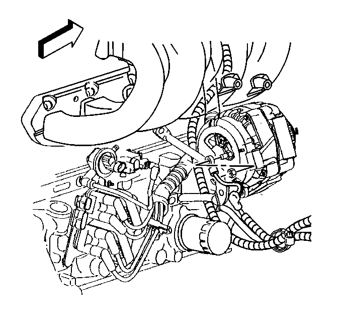
  46. Disconnect the electrical connection from the generator.
  47. Disconnect the generator output wire from the generator.
  48. Move the engine wiring harnesses aside.
  49. Disconnect the fuel pipes from the fuel rail. Refer to Fuel Hose/Pipes Assembly Replacement in Engine Controls.

  50. Object Number: 384387  Size: SH
  51. Install a suitable engine lifting device to the engine lift brackets.

  52. Object Number: 2491  Size: SH
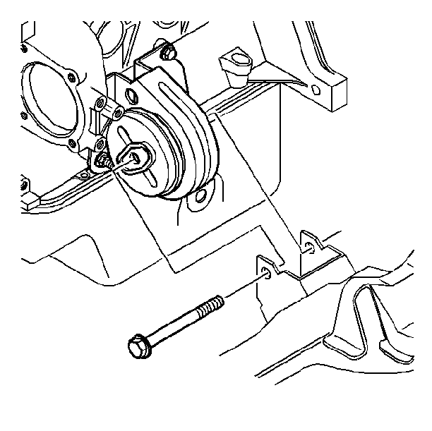
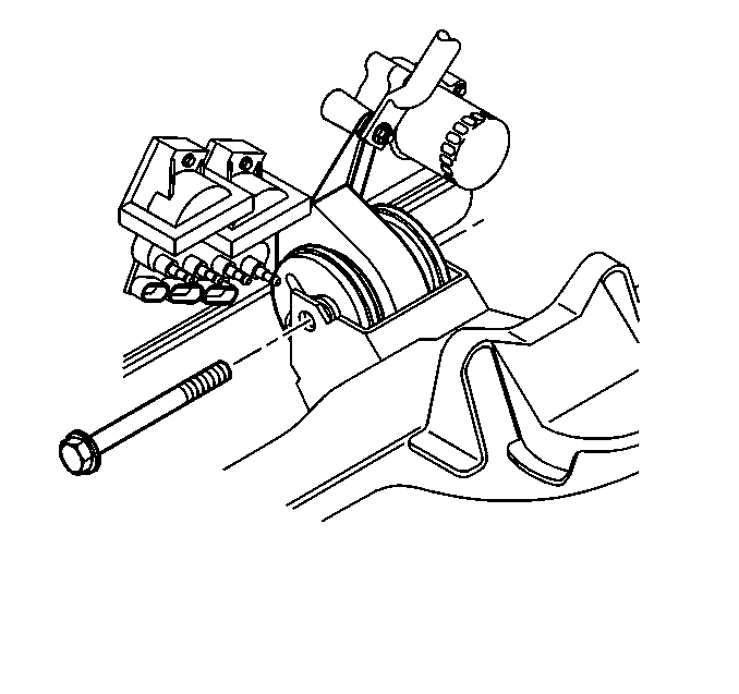
  53. Remove the left side engine mount through-bolt.

  54. Object Number: 3440  Size: SH
  55. Remove the right side engine mount through-bolt.
  56. Remove the engine from the vehicle.

Installation Procedure

  1. Install the engine to the vehicle.
  2. Install the right side engine mount through-bolt. Refer to Engine Mount Replacement .
  3. Install the left side engine mount through-bolt. Refer to Engine Mount Replacement .

  4. Object Number: 384387  Size: SH
  5. Remove the engine lifting device from the engine lift brackets.
  6. Connect the fuel pipes to the fuel rail. Refer to Fuel Hose/Pipes Assembly Replacement in Engine Controls.
  7. Object Number: 395650  Size: SH
  8. Position the engine wiring harnesses.
  9. Notice: Use the correct fastener in the correct location. Replacement fasteners must be the correct part number for that application. Fasteners requiring replacement or fasteners requiring the use of thread locking compound or sealant are identified in the service procedure. Do not use paints, lubricants, or corrosion inhibitors on fasteners or fastener joint surfaces unless specified. These coatings affect fastener torque and joint clamping force and may damage the fastener. Use the correct tightening sequence and specifications when installing fasteners in order to avoid damage to parts and systems.

  10. Connect the generator output wire to the generator.
  11. Tighten
    Tighten the nut to 20 N·m (15 lb ft).

  12. Connect the generator electrical connector.
  13. Connect the engine block heater, if equipped.
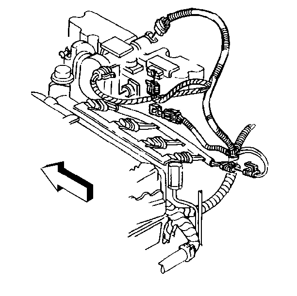
  14. Object Number: 5659  Size: SH
  15. Connect the following electrical connectors to the top of the engine:
  16. • Fuel injector harness
    • Engine coolant temperature (ECT) sensor
    • Idle air control (IAC) motor
    • Manifold absolute pressure (MAP) sensor
    • Throttle position (TP) sensor
  17. Connect the 12 volt supply to the mega fuse.
  18. Connect the battery positive cable to the battery. Refer to Battery Cable Replacement in Engine Electrical.
  19. Caution: In order to avoid possible injury or vehicle damage, always replace the accelerator control cable with a NEW cable whenever you remove the engine from the vehicle.

    In order to avoid cruise control cable damage, position the cable out of the way while you remove or install the engine. Do not pry or lean against the cruise control cable and do not kink the cable. You must replace a damaged cable.

  20. Install a NEW accelerator control cable.
  21. Refer to Accelerator Control Cable Replacement in Engine Controls.

  22. Connect the cruise control cable to the throttle body, if equipped. Refer to Cruise Control Cable Replacement in Cruise Control.
  23. Install both heater hoses to the heater core. Refer to Heater Hoses Replacement in Heating and Ventilation (Non-A/C).
  24. Install the power steering pump. Refer to Power Steering Pump Replacement in Power Steering Systems.
  25. Install the air conditioning compressor, if equipped. Refer to Air Conditioning Compressor Replacement in HVAC Systems with A/C - Manual.
  26. Install the drive belt. Refer to Drive Belt Replacement .
  27. Install the radiator. Refer to Radiator Replacement in Engine Cooling.
  28. Install the air intake duct. Refer to Air Cleaner Inlet Duct Replacement in Engine Controls.
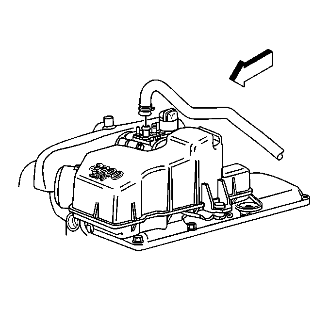
  29. Object Number: 346145  Size: SH
  30. Connect the vacuum brake booster hose.
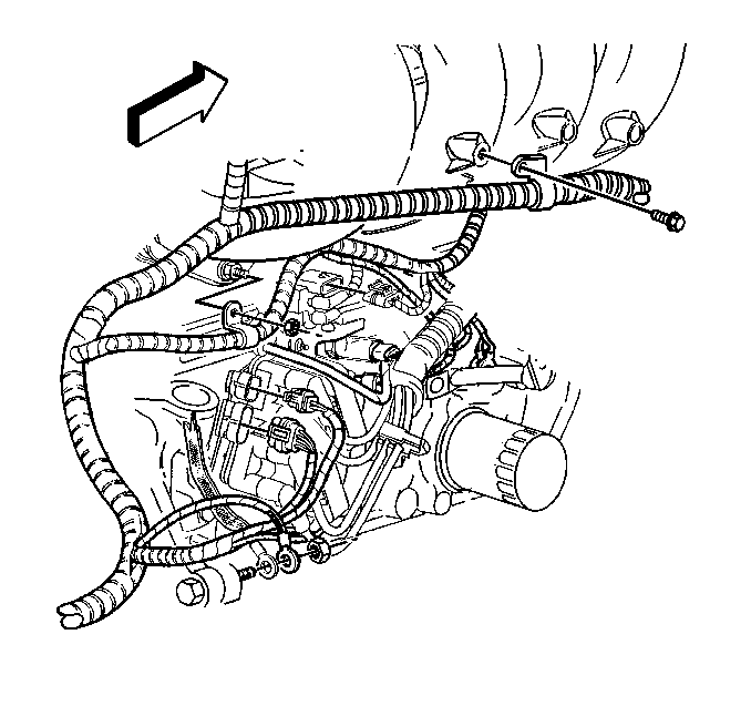
  31. Object Number: 354625  Size: SH
  32. Raise the vehicle.
  33. Install the bolt holding the engine wiring harness to the intake manifold
  34. Tighten
    Tighten the engine wiring harness bolt to 12 N·m (106 lb in).

  35. Install the nut holding the engine wiring harness bracket to the rear lower intake stud.
  36. Tighten
    Tighten the engine wiring harness bracket nut to 30 N·m (22 lb ft).
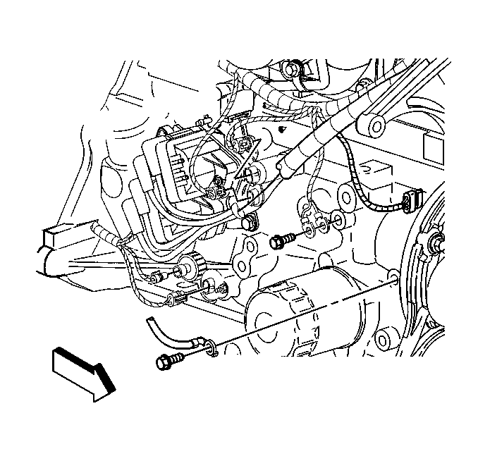

    Object Number: 354620  Size: SH
  37. Connect the following electrical connectors to the right side of the engine:
  38. • Engine oil pressure sensor
    • Camshaft position (CMP) sensor
    • Ignition control module (ICM)
    • EVAP purge canister solenoid valve
    • Crankshaft position (CKP) sensor
    • Knock (KS) sensor
  39. Install the bolt and the ground wires to the engine.
  40. Tighten
    Tighten the ground wire bolt to 35 N·m (26 lb ft).

  41. Install the bolt and the battery negative cable to the engine.
  42. Tighten
    Tighten the battery negative cable bolt to 35 N·m (26 lb ft).

    Object Number: 43037  Size: SH
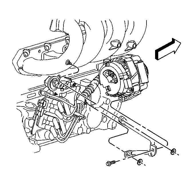
  43. Install the generator brace using the following procedure.
  44. 28.1. Install the brace to the engine.
    28.2. Install the two nuts holding the brace to the engine.
    28.3. Install the bolt to the rear of the generator.

    Tighten
    Tighten the generator rear brace nuts and bolt to 25 N·m (18 lb ft).

  45. Install the right fender wheelhouse extension. Refer to Wheelhouse Extension Replacement in Body Front End.
  46. Connect the oxygen sensor electrical connector. Refer to Oxygen Sensor Replacement in Engine Controls.
  47. Install the transmission.
  48. • Refer to Transmission Replacement in Manual Transmission - NV 1500.
    • Refer to Transmission Replacement in Automatic Transmission - 4L60-E.
  49. Install the starter motor. Refer to Starter Motor Replacement in Engine Electrical.
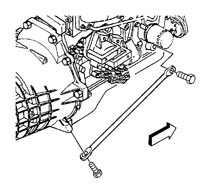
  50. Object Number: 33772  Size: SH
  51. Install the brace rods to the transmission and the engine, manual transmission only.
  52. Tighten
    Tighten the brace bolts to 50 N·m (37 lb ft).
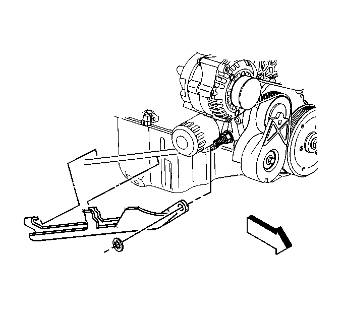

    Object Number: 354503  Size: SH
  53. Install the oil filter drain deflector on the brace rod, if equipped.
  54. Connect the catalytic converter to the exhaust pipe. Refer to Catalytic Converter Replacement in Engine Exhaust.
  55. Connect the exhaust pipe to the exhaust manifold. Refer to Exhaust Manifold Pipe Replacement in Engine Exhaust.
  56. Lower the vehicle.
  57. Install the manual transmission shift lever, if removed. Refer to Shift Lever in Manual Transmission - NV 1500.
  58. Install the hood. Refer to Hood Replacement in Body Front End.
  59. Connect the battery negative cable. Refer to Battery Replacement in Engine Electrical.
  60. Fill the crankcase with oil. Refer to Engine Oil and Oil Filter Replacement
  61. Fill the cooling system with coolant. Refer to Cooling System Draining and Filling in Engine Cooling.
  62. Operate and test the engine. Refer to Engine Set-Up and Testing .