GM Service Manual Online
For 1990-2009 cars only
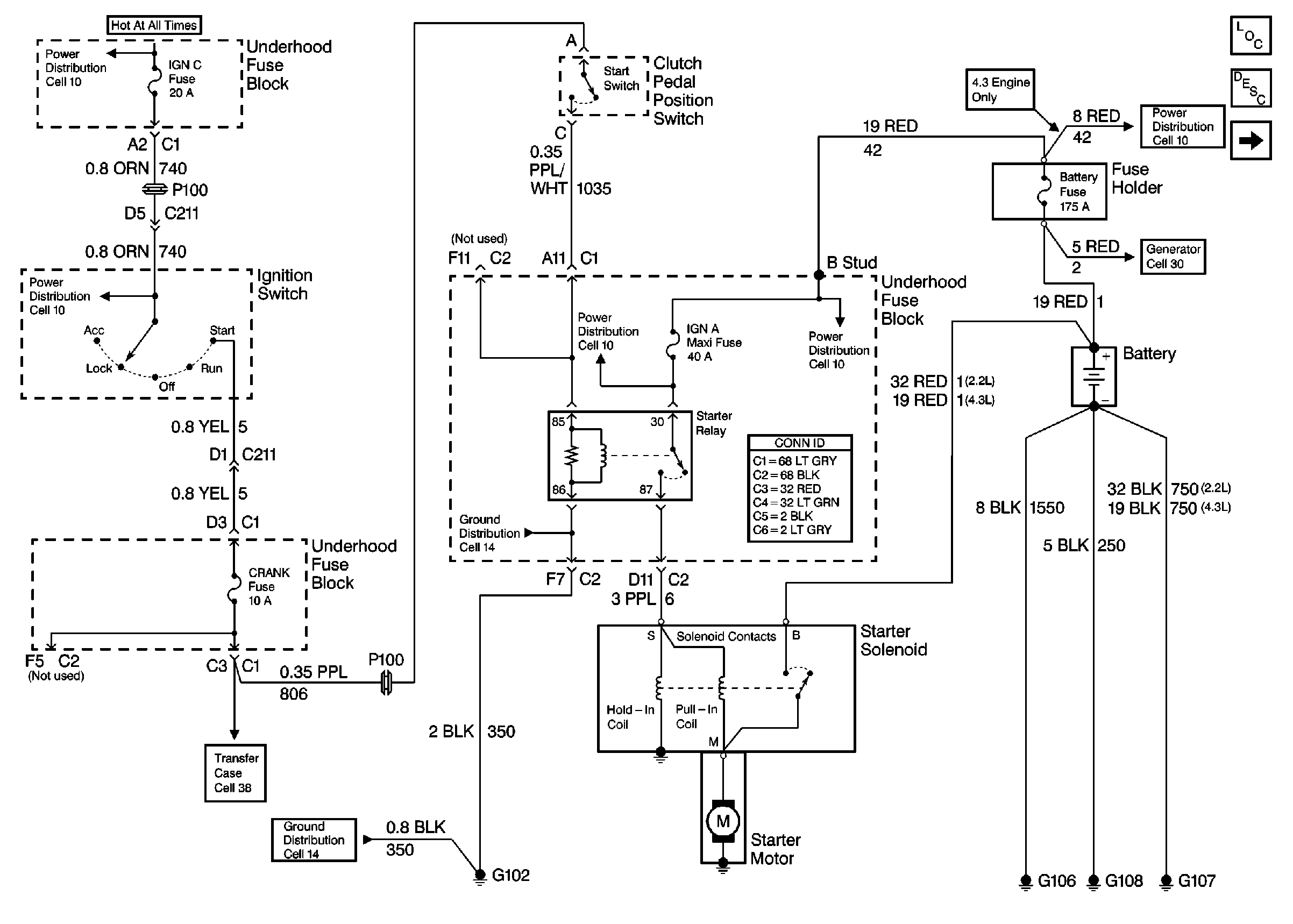
Figure 1:

Cell 30: Manual Transmission Starting


Object Number: 408357  Size: FS
Cell 10: IGN C, IGN A Fuses and Ignition Switch
Cell 38: Power, Front Axle Switch and Vehicle Control Module (VCM)
Cell 14: Underhood Grounds
Power and Grounding Connector End Views
Cell 10: IGN C, IGN A Fuses and Ignition Switch
Cell 10: B+ Buss Bar
Cell 30: Engine Charging
Engine Electrical Components
Starting System Circuit Description
Cell 30: Automatic Transmission Starting
Cell 14: G102
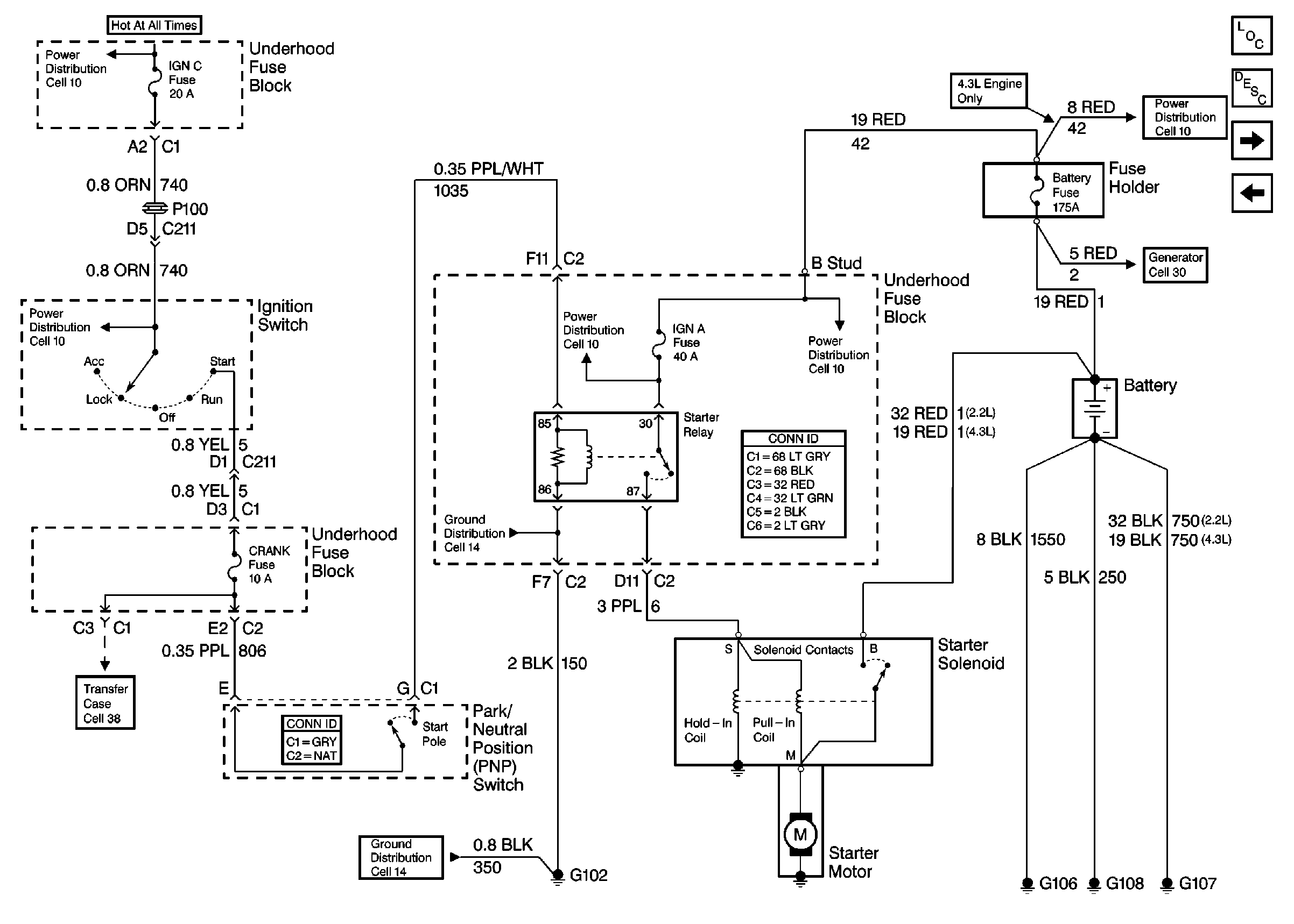
Figure 2:

Cell 30: Automatic Transmission Starting


Object Number: 408355  Size: FS
Cell 10: IGN C, IGN A Fuses and Ignition Switch
Cell 38: Power, Front Axle Switch and Vehicle Control Module (VCM)
Tilt Wheel/Column Connector End Views
Cell 14: Underhood Grounds
Cell 10: IGN C, IGN A Fuses and Ignition Switch
Power and Grounding Connector End Views
Cell 10: B+ Buss Bar
Engine Electrical Components
Starting System Circuit Description
Cell 30: Engine Charging
Cell 30: Manual Transmission Starting
Cell 30: Engine Charging
Cell 14: G102
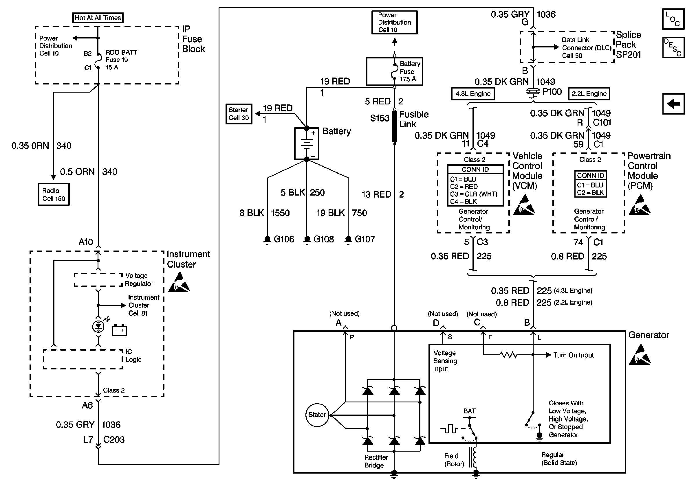
Figure 3:

Cell 30: Engine Charging


Object Number: 408354  Size: FS
Cell 10: AUX PWR, RDO BAT, HDLP SW Fuses and Inadvertent Power Lamp Relay
Cell 150: ILLUM, RDO IGN and RDO BATT Fuses and VSS Signal
Handling ESD Sensitive Parts Notice
Cell 81: Power
Cell 30: Automatic Transmission Starting
Cell 10: B+ Buss Bar
Handling ESD Sensitive Parts Notice
VCM Connector End Views
Powertrain Control Module Connector End Views
Handling ESD Sensitive Parts Notice
Cell 50: SP201 (2.2L)
Engine Electrical Components
Charging System Operation
Cell 30: Automatic Transmission Starting