GM Service Manual Online
For 1990-2009 cars only
Makes
🢒
Isuzu
🢒
1999
🢒
S/T Isuzu - 2WD
🢒
Brakes
🢒
Antilock Brake System
🢒 Antilock Brake System Schematics
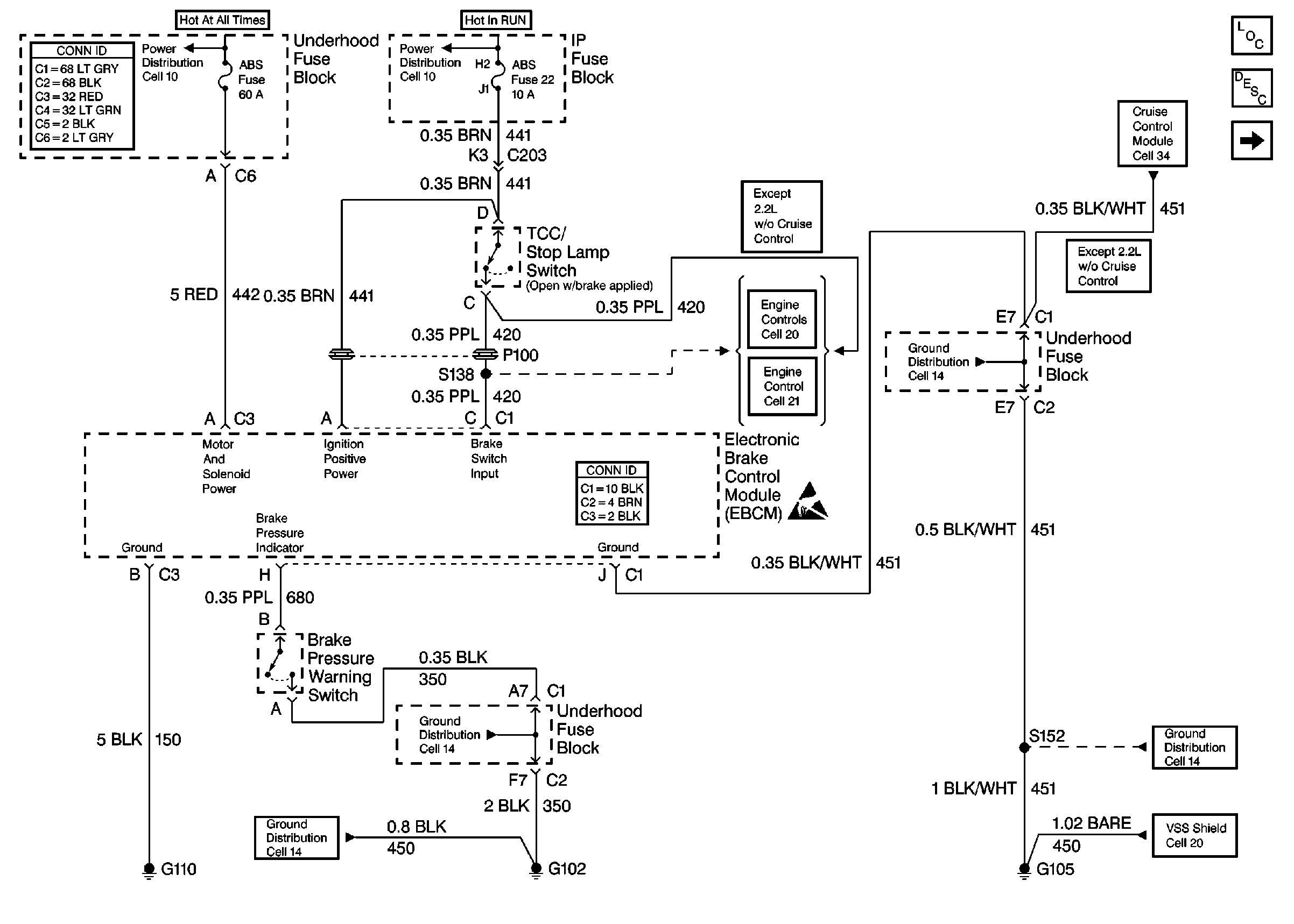
Figure
1:
Cell 44: Power and Ground
Power and Grounding Connector End Views
Cell 10: STUD 2, ABS and TBC Fuses
Cell 10: FRT WPR and ABS Fuses
Cell 21: TCC/Stop Lamp Switch Input
Antilock Brake System Connector End Views
Handling ESD Sensitive Parts Notice
Cell 34: CRUISE Fuse, Multifunction Switch and Cruise Control Module
ABS Components
ABS Description
Cell 44: Class 2 Communication
Cell 14: G103 and G105 (4.3L)
Cell 20: Vehicle Speed Sensor Signal
Cell 14: Underhood Grounds
Cell 14: G102
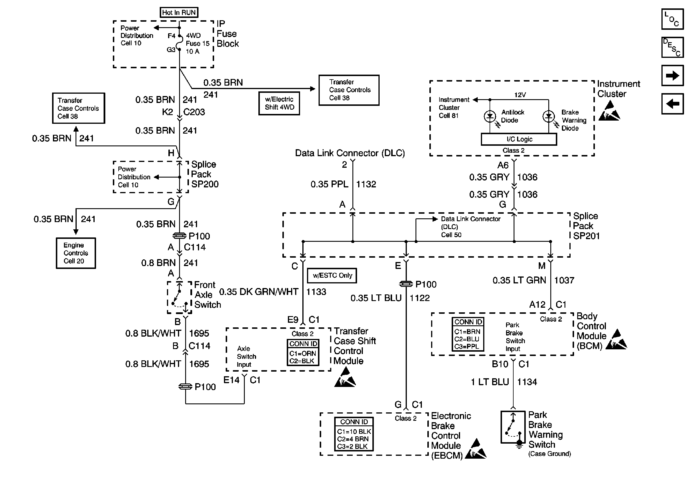
Figure
2:
Cell 44: Class 2 Communication
ABS Components
ABS Description
Cell 44: Wheel Speed Sensors
Cell 44: Power and Ground
Handling ESD Sensitive Parts Notice
Cell 38: Power, Front Axle Switch and Vehicle Control Module (VCM)
Cell 20: Vehicle Speed Sensor Signal
Cell 10: 4WD Fuse
Cell 10: 4WD Fuse
Cell 38: Power, Transfer Case Select Switch and Body Control Module(BCM)
Cell 50: SP201 (2.2L)
Body Control System Connector End Views
Antilock Brake System Connector End Views
Transfer Case Control Connector End Views
Cell 81: VCM/PCM, DLC and SRS
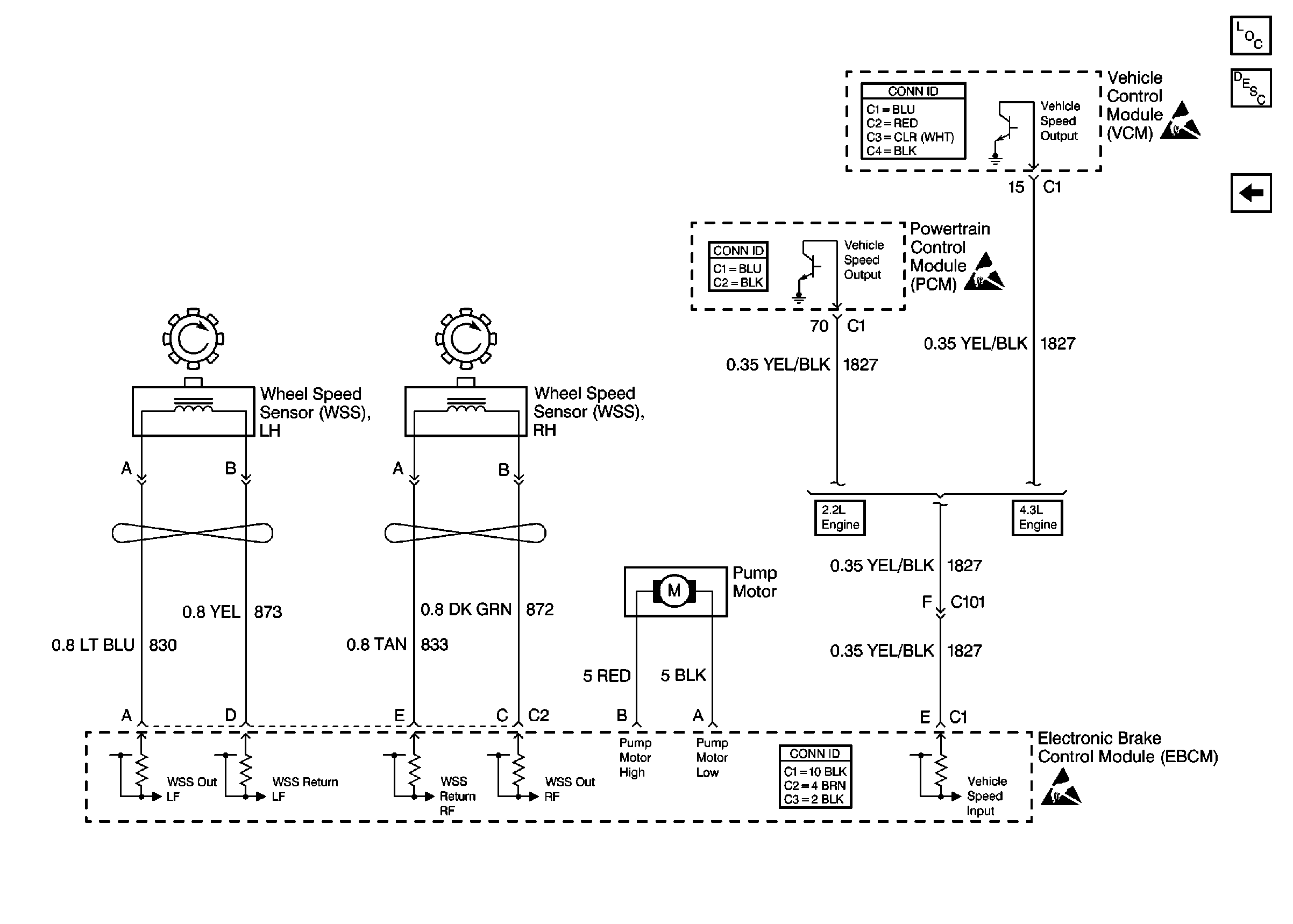
Figure
3:
Cell 44: Wheel Speed Sensors
VCM Connector End Views
Handling ESD Sensitive Parts Notice
ABS Components
ABS Description
Cell 44: Class 2 Communication
Handling ESD Sensitive Parts Notice
Powertrain Control Module Connector End Views
Antilock Brake System Connector End Views
Handling ESD Sensitive Parts Notice