Composite Headlamps
Turn the adjustment screws in order to make horizontal
or vertical adjustments. Access the adjustment screws through the top of the
radiator grille with the hood raised.
The vertical adjustment screw is located on the outboard side of the
headlamp. Turn the vertical adjustment screw clockwise in order to raise the
aim of the headlamp. Turn the adjustment screw counter-clockwise in order
to lower the aim of the headlamp.
Turn the horizontal adjustment screw clockwise in order to move the
aim of the headlamp inboard. Turn the horizontal adjustment screw counter-clockwise
in order to move the aim of the headlamp outboard.
Adjustment Procedure
Tools Required
J 25300-A Safety
Aimer
Some state and local authorities have specific requirements for aiming
headlamps. Follow these requirements. Replacement of a headlamp will not
normally require an aiming adjustment. However, inspect the alignment.
Use the J 25300-A
or an equivalent. Instructions are supplied by the tool manufacturer.
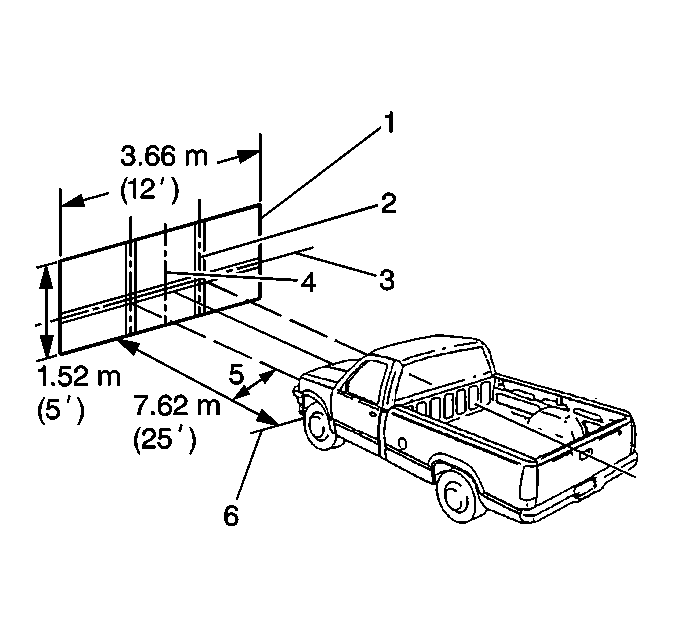
If no special tools are available, use the screen method.
| • | Have a specific aiming area in a darkened location. |
| • | Ensure that the area is large enough to accommodate the vehicle,
plus an additional 7.62 m (25 ft), as measured from the front
surface of the headlamp to the surface of the screen. |
| • | Ensure that the floor on which the vehicle rests is level with
the bottom of the screen. Compensate as necessary if the floor is not level. |
| • | Ensure that the aiming screen meets the following requirements: |
| - | The screen is at least 1.52 m (5 ft) high by 3.66 m
(12 ft) wide. |
| - | The screen has a matte white surface. |
| - | The screen is well shaded from extraneous light. |
| - | The screen is properly adjusted in relation to the floor. |
| - | The screen has a vertical center line. |
| - | The screen has 2 laterally adjustable vertical tape lines. |
| - | The screen has a vertically adjustable horizontal tape line. |
| - | If a regular commercial aiming screen is not available, the screen
may consist of a vertical wall having an uninterrupted area approximately
1.52 m (5 ft) high by 3.66 m (12 ft). Ensure
that the wall is finished with a washable flat white paint. |
Important:
| • | For each vehicle inspected, the horizontal tape line on the screen
must be adjusted. Vehicles of the same model and year may have different heights
for the headlamps. |
| • | Make provisions for moving the screen in order to align the screen
parallel with the rear axle. |
| • | Once the screen is set up in a permanent location, paint a reference
line on the floor in order to mark the proper location of the headlamps when
the headlamps are being aimed. |
- Position the vehicle squarely with the screen (1). Ensure that
the front surfaces of the headlamps are 7.62 m (25 ft) from
the aiming screen.

- Ensure that all vehicle components are properly installed if other
work has been performed on the vehicle.
- Ensure that the vehicle has 1/3 tank of fuel or less.
- Close all of the vehicle's doors.
- Rock the vehicle in order to stabilize the suspension.
- Align the centerline of the vehicle with the vertical centerline
on the screen.
| • | Mark the center of the top edge of the front and rear windows
with tape. |
| • | Use these lines as sights in order to align the vertical centerlines
of the vehicle with the screen. |
- Adjust the distance between the vertical center line and the vertical
tape lines on the aiming screen to correspond with the distance between the
floor and the horizontal centerline of the low beam headlamps.
- Adjust the height of the horizontal tape line on the aiming screen
in order to match the distance between the floor and the horizontal centerline
of the low beam headlamps.
- Turn on the low beam headlamps. Observe the left and top edges
of the high intensity zones on the aiming screen.
| • | The top edge of each high intensity zone must be within 75 mm
(3 in) above to 75 mm (4 in) below the horizontal centerline. |
| • | The left edge of each high intensity zone must be within 100 mm
(4 in) either side of the vertical centerlines. |

