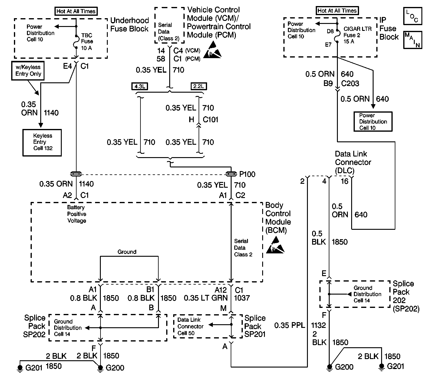
Circuit Description
The Passlock™ system is designed in order to prevent vehicle operation if the current ignition key is not used in order to start the vehicle. The ignition key will allow the lock cylinder to turn. Once the lock cylinder turns, the Passlock™ sensor (located inside the ignition switch assembly) sends an analog voltage code to the body control module (BCM). If the BCM receives the correct analog voltage code from the Passlock™ sensor, the BCM sends a Class 2 message to the powertrain control module (PCM)/vehicle control module (VCM). The PCM/VCM then enables fuel delivery.
The body control module (BCM) supplies the following items to the Passlock™ sensor:
| • | A 12 volt supply voltage |
| • | A data line |
| • | A ground circuit |
For additional information on the security telltale, refer to Security Lamp State in Scan Tool Data Definitions .
Diagnostic Aids
You must diagnose the diagnostic trouble codes in the order specified in the Passlock™ system diagnostic trouble code list. Failure to do so may result in the following conditions:
| • | Extended diagnostic time |
| • | Incorrect diagnosis |
| • | Incorrect parts replacement |
Test Description
The numbers below refer to the step numbers on the diagnostic table.
-
This test inspects for a malfunction related to the instrument panel cluster (IPC) preventing the SECURITY telltale bulb inspection. If this malfunction is due to an open GAUGES fuse, the SECURITY telltale will not turn ON and the engine will not run.
-
The SECURITY telltale will turn ON and remain ON when the ignition switch is in the RUN position and a Passlock™ DTC is currently detected.
-
This test inspects for a tamper condition. The engine will not run while the SECURITY telltale is flashing and the tamper timer is running. Refer to Tamper Timer in Scan Tool Data Definitions for more information.
-
This test inspects for a malfunction that prevents communication between the IPC and the body control module (BCM). This condition causes the security telltale to remain ON when the ignition switch is turned to the OFF position.
-
This operation of the SECURITY telltale indicates that Passlock™ DTCs exist. If the scan tool is operating properly and indicates that no Passlock™ DTCs exist, the BCM may be malfunctioning.
-
This condition indicates an open in the Passlock™ sensor circuits. If the powertrain parameter VTD Fuel Disable displays ACTIVE during or immediately following cranking, the sensor circuits are also open. This condition is tested in the DTC B2958 diagnostic table. Refer to DTC B2958 Security System Sensor Data Circuit High .
-
When the SECURITY telltale successfully completes the bulb inspection and the engine starts and runs properly, the Passlock™ system is operating correctly with no malfunctions present.
Step | Action | Value(s) | Yes | No |
|---|---|---|---|---|
Turn the ignition switch to the RUN position. Does the SECURITY telltale turn ON? | -- | Go to Step 2 | Go to Instrument Cluster System Check in Instrument Panel, Gauges and Console | |
Does the SECURITY telltale turn ON and remain ON for more than 5 seconds? | -- | Go to Step 5 | Go to Step 3 | |
Does the SECURITY telltale turn ON for 3 seconds, turn OFF briefly, and then flash ON and OFF? | -- | Go to Step 5 | Go to Step 4 | |
Does the SECURITY telltale turn ON for 3 seconds, turn OFF for 2 seconds, then turn ON steady? | -- | Go to Step 1 | Go to Step 9 | |
5 | Connect a scan tool to the data link connector (DLC). Does the scan tool power up? | -- | Go to Step 7 | Go to Step 6 |
6 |
Are the repairs complete? | -- | Go to Step 1 | -- |
7 |
Does the scan tool display No Communication with Vehicle? | -- | Go to Step 6 | Go to Step 8 |
Are any Passlock™ DTCs present? | -- | Go to the applicable DTC table Diagnostic Trouble Code (DTC) Displaying | Go to Step 1 | |
Does the scan tool display a value of OPEN for the Passlock™ code? | -- | Go to Step 10 | ||
10 | Attempt to start the vehicle. Does the engine crank fast enough in order to start the vehicle? | -- | Go to Step 11 | Refer to Starting System Check in Engine Electrical |
Does the engine start and run? | -- | System OK | Refer to Powertrain On Board Diagnostic (OBD) System Check (2.2L), or refer to Powertrain On Board Diagnostic (OBD) System Check (4.3L) in Engine Controls |
