Key Identification and Usage
A single key is used for all of the locks on the vehicle. The key identification
is obtained from the four-character key code located on the key tag. The four
character key code should be recorded by the owner and the dealer. The mechanical
key code can be determined through the use of a code cross-reference list
which is available to owners of key cutting equipment from the equipment suppliers.
If the mechanical key code is needed and the four character key code is not
available, the mechanical key code can be determined by placing the key directly
on the key code diagram.
Cutting Keys
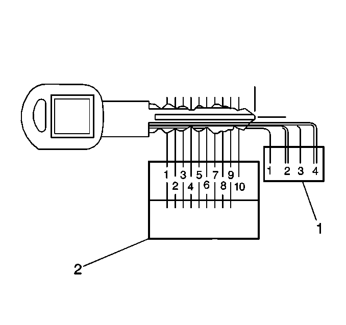
After the mechanical key code has been determined from the code list
or the key code diagram, perform the following steps:
- Cut a blank key to the proper level (1) of each of the tumbler
positions (2).
- Inspect the key operation in the lock cylinder.
Replacement Lock Cylinders
The lock cylinder keyway is designed so that other model keys will not
enter a current model lock cylinder. New lock cylinders are available from
the service parts warehouses without tumblers and springs. The tumblers and
springs are also available and must be assembled into the lock cylinder according
to the mechanical key code.
Lock Cylinder Tumbler Operation
All lock tumblers are shaped alike with the exception of the notched
position on one side. As the key is inserted into the lock cylinder, the tumblers
are lowered to the correct height so that notches on each tumbler are at the
same level. When the notches on all six tumblers line up, two small springs
push the side bar into the notches, allowing the cylinder to turn in the cylinder
bore. Five types of tumblers are used in making the lock combinations. Each
tumbler is coded and stamped with a number between 1 and 5.
Ignition Lock Cylinder Coding
Tools Required
J 41340 Lock Cylinder
Staking and Holding Fixture
Important: If the original ignition lock cylinder is being RECODED, proceed to
Step 1. If the ignition lock cylinder is being REPLACED with a new ignition
lock cylinder, proceed to Step 2.
- Remove of the ignition lock cylinder from the ignition lock cylinder
housing.
| 1.1. | Insert the key into the ignition lock cylinder. |
| 1.2. | Rotate the key to START. |
| 1.3. | Press the lock cylinder retainer located in the end of the ignition
lock cylinder. |
| 1.4. | Pull the ignition lock cylinder out of the lock cylinder housing
using the key. |
- Pry the tumbler spring retainer out of the ignition lock cylinder
using a small flat-bladed tool.
- Remove all of the tumbler springs.
- Remove all of the tumblers by rotating the lock cylinder so that
the tumbler slots are facing down. Pull the side bar out with your fingers
and tap the lock cylinder on a hard surface.
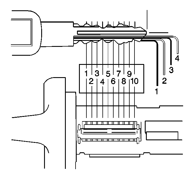
- Determine the tumbler
numbers/arrangement:
| 5.1. | Place the tip of the key directly over the tip of the illustrated
key. |
| 5.2. | Inspect that the diagram outlines the key. |
| 5.3. | Starting with position 1 (the open end of the lock cylinder),
find and record the lowest level (tumbler number) that is visible. |
| 5.4. | Repeat the previous step for positions 2-10. |
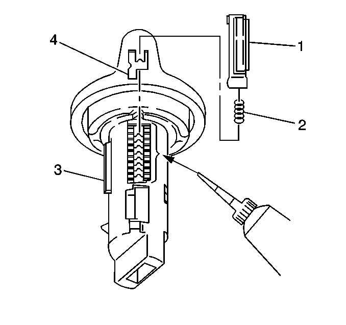
- Starting with position
1, insert the tumblers (4) into their corresponding slots in the coded order.
- Using your fingers, pull out the side bar (3) until the tumblers
fall completely into place.
- Insert one tumbler spring (2) above each tumbler (4).
- Lubricate the tumblers using 5W-30 motor oil or equivalent.
- Insert the spring retainer (1) prongs into their respective slots
in the lock cylinder.
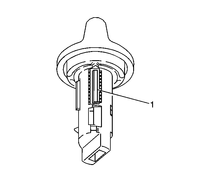
- Press the retainer (1)
down until the lock cylinder is fully seated in the lock cylinder.
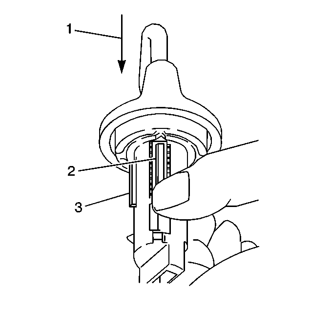
- Inspect for proper tumbler
installation:
| 12.1. | Hold the spring retainer (2) in position. |
| 12.2. | Insert the key (1) into the lock cylinder. |
| 12.3. | The side bar (3) should drop down flush with the lock cylinder
diameter. |
| 12.4. | If the side bar does NOT drop down flush with the lock cylinder
diameter, proceed to Step 2. |
- Remove the key.
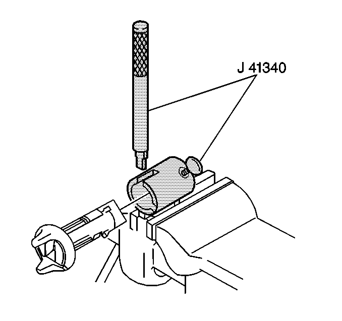
- Secure the lock cylinder
in the J 41340
.
| 14.1. | Inspect that the spring retainer is facing up and positioned directly
under the punch slots. |
| 14.2. | Push the lock cylinder into the J 41340
(1) until butted with the lock cylinder bezel. |
| 14.3. | Tighten the J 41340
holding screw. |
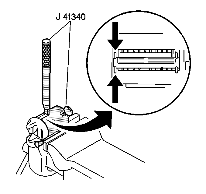
- Stake the bezel end of
the spring retainer:
| 15.1. | Hold the flat side of the punch squarely against the face of the
lock cylinder bezel. |
| 15.2. | Stake the lock cylinder metal over the spring retainer prong. |
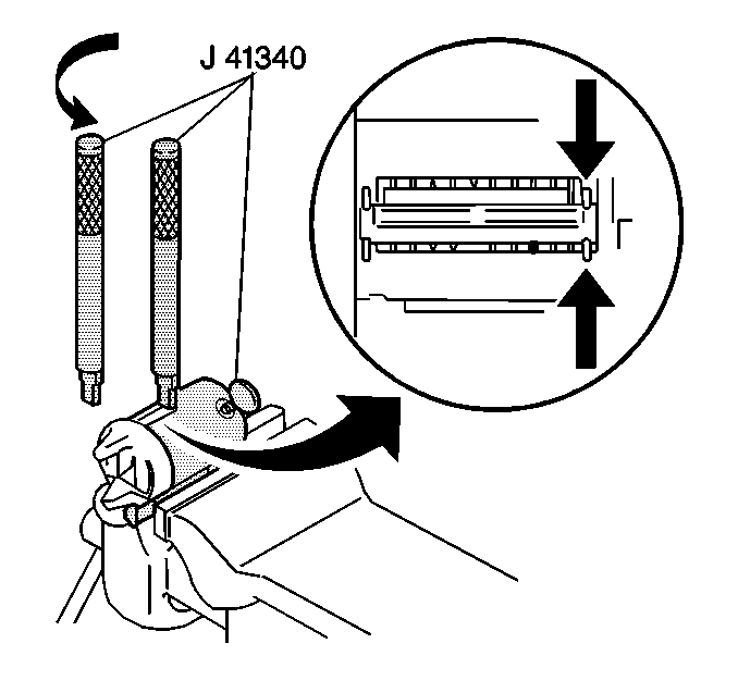
- Stake the opposite end
of the spring retainer:
| 16.2. | Rotate the J 41340
punch 180 degrees. |
| 16.3. | Hold the J 41340
punch squarely against the end of the punch slot. |
| 16.4. | Stake the lock cylinder metal over the spring retainer prong. |
- Loosen the J 41340
holding screw.
- Remove the lock cylinder from the J 41340
.
- Inspect that the spring retainer is properly staked. Repeat staking
as needed.
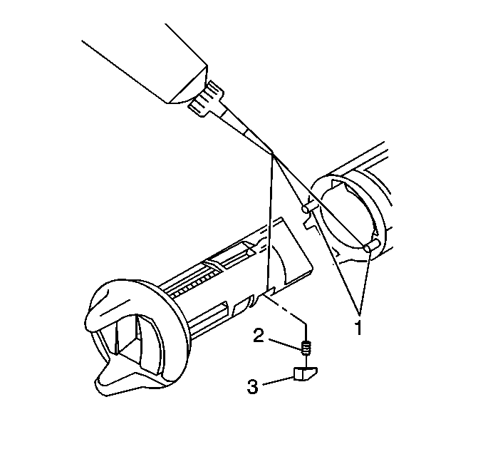
- Lubricate the lock cylinder retainer slot.
- Insert the following parts into the lock cylinder retainer slot:
| • | the lock cylinder retainer spring (2) |
| • | the lock cylinder retainer (3) |
- Lubricate the following parts with 5W-30 motor oil or equivalent:
| • | the lock cylinder housing detent pins (1) |
| • | the lock cylinder retainer (3) |
- Orient the lock cylinder retainer to the tapered notch in the
lock cylinder housing.
- Insert the ignition lock cylinder into the ignition lock cylinder
housing.
- Inspect for proper ignition lock cylinder rotation using the key.
Important: Body Control Module (BCM) codes will be stored and the vehicle will
not start If the ignition lock cylinder was REPLACED and an attempt is made
to start the vehicle prior to performing the theft deterrent relearn procedure.
- Perform the theft deterrent relearn procedure if the ignition lock cylinder
was REPLACED. Refer to
PASSLOCK Reprogramming Auto Learn
in Theft Deterrent.
Coding All Lock Cylinders Except Ignition Lock Cylinder
All of the vehicle's lock cylinders, except the ignition lock cylinder,
use a maximum of five tumblers.
- Determine the lock cylinder tumbler numbers and their positions.
- Install the appropriate tumblers accordingly.
- Install the lock cylinder cap (If applicable) to the lock cylinder.
Refer to the Capping Procedure for Lock Cylinders with Press-On Caps or the
Capping Procedure for Lock Cylinders without Press-On Caps.
- Install the lock cylinder actuator arm and retainer on the back
of the cylinder (if applicable).
Capping Procedure for Lock Cylinders with Press-On Caps
- Hold the lock cylinder so that the lock cylinder key opening is
facing up.
- Install the lock cylinder door springs and the lock cylinder door
to the lock cylinder.
- Install the lock cylinder cap over the lock cylinder door and
press the lock cylinder cap down until it snaps into place.
Capping Procedure for Lock Cylinders without Press-On Caps
- Hold the lock cylinder so that the lock cylinder opening is facing
up.
- Install the lock cylinder door springs and the lock cylinder door
to the lock cylinder.
- Press and hold the lock cylinder cap down on the lock cylinder.
The lock cylinder cap must be completely seated to the lock cylinder.
Important: Make sure that the lock cylinder cap is held tight against the lock
cylinder while turning the lock cylinder over so that the lock cylinder door
springs do not fall out.
- Hold the lock cylinder cap against the lock cylinder, turn the lock
cylinder over and place it face down on a surface that will allow for capping
and will not scratch the lock cylinder cap.
- Using a blunt-ended tool, fold any two opposing lock cylinder
cap tabs over the edge of the lock cylinder.
- Inspect for proper positioning of the lock cylinder door and the
lock cylinder cap by inserting the key into the lock cylinder.
- If the lock cylinder door and cap are positioned properly, fold
the remaining lock cylinder cap tabs over the edge of the lock cylinder. If
the lock cylinder door and cap are not positioned properly, repeat the capping
procedure.


