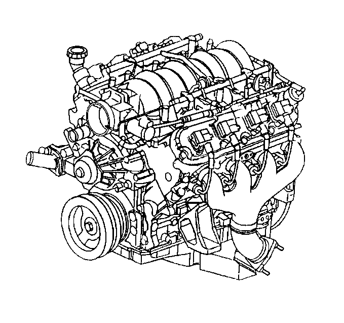
Engine vibration is usually due to one or more of the following conditions:
| • | First-order engine imbalance |
| • | Inherent engine firing sequence |
| • | Inherent shaking engine forces |
| • | Engine-driven accessories |
Because these vibrations are engine-speed related, they are also normally torque sensitive. These vibrations may appear and disappear at different vehicle or road speeds, but will always appear at the same engine speed.
For example, if a customer states that a vibration is present at 40 km/h (25 mph), 64 km/h (40 mph), and again at 104 km/h (65 mph), and that the symptoms of the vibration are similar at all of these speeds, the vibration is probably engine-speed related. Any disturbance or vibration that is present during the following road tests would be considered engine-speed related:
| • | The Neutral run-up test |
| • | The downshift test |
| • | The brake torque test |
Any vibration that is present during the Neutral coast-down test is not engine-speed related. The engine-related vibrations covered in this diagnosis are engine-speed sensitive only.
First-Order Engine Imbalance
Notice: Do not accelerate against the brakes for longer than 10 seconds. Do not overheat the engine or the transmission. Depending on the vehicle design, the engine will only accelerate to a certain point under these conditions. Also, care should be taken during diagnosis as some disturbances may be created during brake torque that normally do not exist.
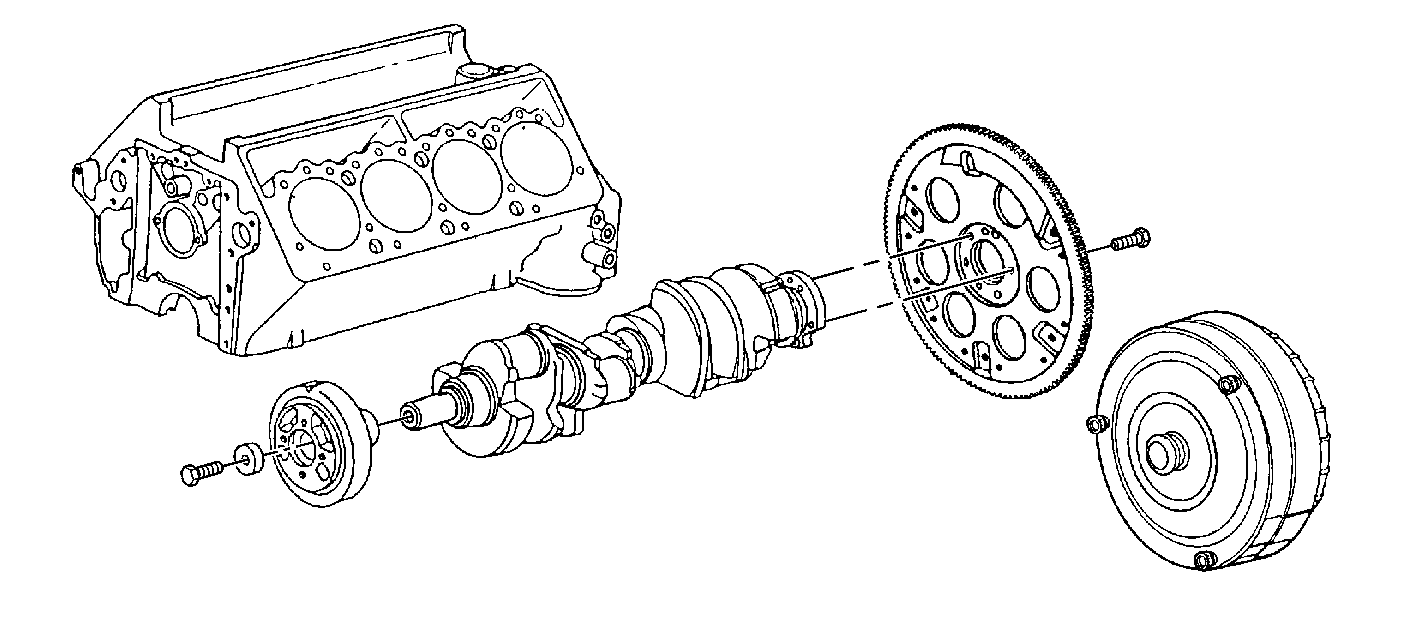
Notice: Proper flywheel installation requires carefully WALKING the flywheel onto the crankshaft and stagger-tightening the bolts. Proper torque converter to flywheel installation then requires gradually WALKING the torque converter to be flush with the flywheel, prior to installing the bolts. Do not draw the torque converter to the flywheel with the bolts. If these precautions are not followed, warping or bending of the flywheel and/or damage to the transmission torque converter may result.

Engine imbalance is a condition that exists when a component that rotates at crankshaft speed is either unbalanced or has excessive runout. In rare cases, the crankshaft may be unbalanced. Balancing the component or correcting the runout may bring the disturbance to an acceptable level.
Symptoms
| • | Vehicle shake at low speeds of 500-1,200 rpm, or 8-20 Hz |
| • | Roughness and BOOM at higher speeds of 1,200-3,000 rpm, or 20-50 Hz |
| • | Vibration usually detected during the Neutral run-up test |
Isolating the Components
- Perform the Neutral run-up test, noting the RPM at which the vibration is the worst, and the most severe. Refer to Types of Road Test .
- Inspect all powertrain mounts. Repair or replace as needed.
- Inspect for any bindings or ground-outs in the exhaust system.
- Mark the location of the torque converter to the flywheel.
- Disconnect the torque converter from the propeller shaft, pushing the converter back from the flywheel.
- Tie up the converter, away from the flywheel.
- Perform the Neutral run-up test again. Refer to Types of Road Test . Observe the flywheel. If the flywheel shows any wobble or lateral runout, replace the flywheel.
- If the vibration still exists, inspect the propeller shaft runout. Refer to Diagnosing First-Order Driveline Vibration .
- If the vibration still exists, inspect the harmonic balancer.
- If the vibration still exists, the problem is related to residual engine imbalance.
Important: Steps 4-17 apply only to vehicles equipped with automatic transmission.
| • | Re-index the torque converter in 3 different positions. |
| • | If the disturbance still exists, replace the torque converter. |
Correcting Residual Engine Imbalance
- Install the washers on the harmonic balancer pulley bolts.
- Replace the bolts with longer bolts of equal hardness as needed.
- Install the J-nuts on the outer edge of the circular holes in the flywheel.
- For M/T only, inspect the flywheel and the pressure plate for the following conditions:
| • | Correct factory indexing (The white paint spot on the flywheel and the pressure plate should line up.) |
| • | Warping |
| • | Balance |
Engine Firing Frequency
Condition | Engine Speed (RPM) | Any Engine First Order (Hz) | 4-Cylinder Second Order (Hz) | 6-Cylinder Third Order (Hz) | 8-Cylinder Fourth Order (Hz) |
|---|---|---|---|---|---|
Shake | 500 750 1000 1500 | 8.3 12.5 16.6 25 | 16.6 25 33.3 50 | 24.9 37.5 49.8 75 | 33.2 50 66.4 100 |
Roughness | 2000 2500 | 33.3 41.6 | 66.6 83.2 | 99.9 124.8 | 133.2 166.4 |
Buzz | 3000 3500 4000 | 50 58.3 66.6 | 100 110.6 132.4 | 150 174.9 199.8 | 200 233.2 266.4 |
Firing frequency is a term used to describe the pulses created as the engine fires each cylinder. All engines have a firing frequency, but the object is to keep these disturbances from entering the passenger compartment. Initially, inspect for the following conditions:
| • | The engine and the exhaust system are mounted in a relaxed position. |
| • | All of the mounts and hangers should be in good condition and correct for the application. |
| • | No components, hoses, or lines are grounding to the frame or to the body. |
Important: The frequency of these disturbances will depend on the number of cylinders. The engine order will always be equal to one-half the number of cylinders. This is because a four-stroke engine requires 2 complete revolutions of the crankshaft in order to fire all of the cylinders.
For example, a V8 engine will fire cylinders 1, 3, 5, and 7 on the first revolution. Cylinders 2, 4, 6, and 8 will fire on the second revolution. This results in 4 firing pulses per revolution of the crankshaft, or fourth order.
Engine Firing Frequency Symptoms
The following are symptoms of engine firing frequency:
| • | The vibration may be torque sensitive. |
| • | The vibration is engine-speed related. |
| • | The vibration is heard as a boom or a moan. |
| • | The vibration is felt as a shake, roughness, or buzz (depending on the number of cylinders). |
| • | The vibration excites the resonance of a system or a component, causing the system or the component to have a narrow rpm range. |
The key to correcting these types of complaints is to isolate the vibration from the passenger compartment or the body.
Engine Firing Frequency-Related Vibration Causing Components
- Inspect for collapsed engine mounts.
- Inspect for a collapsed or broken transmission mount.
- Inspect the exhaust hangers.
- Lubricate the manifold flexible coupling (if applicable).
- Inspect the A/C and P/S lines.
- Inspect the drive belt for whipping.
- Inspect the accessory unit fasteners for damage or looseness.
- Inspect the body panels for missing or loose welds.
- Remove any aftermarket equipment that may complete a transfer path into the passenger compartment.
- Inspect the exhaust system and powertrain mounts. If necessary, re-bed the engine and align the exhaust system as follows:
Replace as needed. Refer to Engine Mount Replacement in Engine Mechanical-2.2L
Replace as needed.
Exhaust systems can expand 1-2 in when hot.
| 3.1. | Remove the hangers one at a time. |
| 3.2. | Adjust or replace as needed. |
| 5.1. | Isolate the hoses from the body. |
| 5.2. | Install the retainers. |
| 10.1. | Loosen the mounts and hangers. |
| 10.2. | Settle the powertrain by shifting from DRIVE to REVERSE. |
| 10.3. | Tighten all fasteners with the powertrain in the relaxed position. |
Some residual vibrations may be normal. Compare the vibrations with a similar vehicle in order to get a feel for what is commercially acceptable, preferably with the customer present. Refer to bulletins for updates on the use of mass damper weights for specific applications.
Inherent Engine Shaking Forces
Engine Order | L3 | L4 (without Balance Shaft) | L4 (with Balance Shaft) | L6 | V6 60° & V6 90° (with Balance Shaft) | V6 90° (without Balance Shaft) | V8 90° |
|---|---|---|---|---|---|---|---|
½ Order Torque Sensitive | Single Cylinder Misfire | Single Cylinder Misfire | Single Cylinder Misfire | Single Cylinder Misfire | Single Cylinder Misfire EGR/Fuel Variance | Single Cylinder Misfire EGR/Fuel Variance | Single Cylinder Misfire |
1st Order Imbalance | Normal | Abnormal | Abnormal | Abnormal | Abnormal | Normal | Abnormal |
1.5 Order Torque Sensitive | Normal | -- | -- | -- | Bank-to-Bank EGR/Fuel Variance | Bank-to-Bank EGR/Fuel Variance | -- |
2nd Order | Normal | Normal | Abnormal | Abnormal | Normal | Normal | Abnormal |
2nd Order Torque Sensitive | -- | Normal | Normal | -- | -- | -- | Bank-to-Bank EGR/Fuel Variance |
3rd Order Torque Sensitive | Normal (Small Amount) | -- | -- | Normal | Normal | Normal | -- |
4th Order Torque Sensitive | -- | Normal (Small Amount) | Normal (Small Amount) | -- | -- | -- | Normal |

Just like firing frequency, some engine disturbances are the result of normal operation. Some engines can have additional inherent vibration due to the following elements:
| • | The cylinder arrangement |
| • | The design |
| • | The firing order |
Before attempting to repair a disturbance, compare the disturbance to another known good vehicle. Although some vibrations could be normal, the vibrations may not be pleasant to the customer.
The key to resolve an inherent engine disturbance is to isolate the vibration from the passenger compartment. Follow the same procedures as outlined for the engine firing frequency-related vibrations.
Engine-Driven Accessories

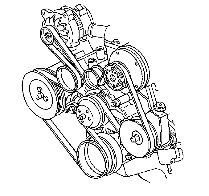
Engine-driven accessories that exhibit vibration pose some special challenges. For example, the drive belts may no longer be removed one at a time in order to isolate the condition. If removing the belt eliminates the vibration, reinstall the belt and operate each accessory one at a time in order to see which has the most effect on the vibration. However, one component may affect another because the drive belt drives all of the accessories.
Inspect the accessory load to ensure that the load is not exciting the engine firing frequency.
Diagnosis
- Compare the vibrations to a known good vehicle in order to ensure they are abnormal.
- Remove the drive belt.
- If the vibration stops, perform the following steps:
- Inspect for accessory load affecting the engine firing frequency.
- Inspect the pulleys for misalignment or bends. Repair or replace as needed.
- Inspect the A/C system for overcharging. Evacuate and recharge as needed. Refer to Refrigerant Recovery and Recharging in HVAC Systems with A/C - Manual.
- Inspect the engine oil level. Add or drain the oil as needed.
| 3.1. | Install the drive belt. |
| 3.2. | Operate each accessory one at a time in order to see which has the most effect on the vibration. |
Diagnosis and Repair of Engine Firing Frequency-Related Vibrations
- Raise and suitably support the vehicle. Refer to Lifting and Jacking the Vehicle in General Information.
- Follow the necessary safety precautions. Refer to
Caution: One or more of the following guidelines may apply when performing specific required tests in the work stall:
in Cautions and Notices.• When a test requires spinning the drive wheels with the vehicle jacked up, adhere to the following precautions: - Do not exceed 56 km/h (35 mph) when spinning one drive wheel with the other drive wheel stopped. This limit is necessary because the speedometer indicates only one-half the actual vehicle speed under these conditions. Personal injury may result from excessive wheel spinning. - If all of the drive wheels are spinning at the same speed, do not exceed 112 km/h (70 mph). Personal injury may result from excessive wheel spinning. - All persons should stay clear of the rotating components and the balance weight areas in order to avoid possible personal injury. - When running an engine in the repair stall for an extended period of time, use care not to overheat the engine and the transmission. • When a test requires jacking up the vehicle and running with the wheels and brake rotors removed, adhere to the following precautions: - Support the suspension at normal ride height. - Do not apply the brake with the brake rotors removed. - Do not place the transmission in PARK with the drive axles spinning. - Turn Off the ignition in order to stop the powertrain components from spinning. • When running an engine in the work stall, use the exhaust removal system to prevent breathing dangerous gases. - Attempt to duplicate the vibration.
- While the vibration is present, find the areas of the vehicle excited by the vibration.
- Inspect for witness marks due to a rubbing component.
- Isolate the component and re-evaluate the vibration.
- Inspect for proper torque on the excited components. Tighten as needed.
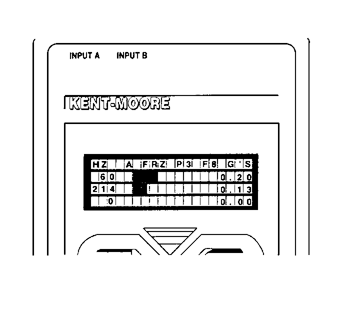
- If the vibration still exists, do a complete engine vibration diagnosis with the EVA.
Engine Vibration Diagnosis with the EVA
- Place the EVA vibration sensor on the seat track rail with the UP label facing upward.
- Plug the EVA into a 12 volt power supply.
- Prepare the EVA for data recording:
- Slowly accelerate until the vibration occurs.
- Remember the vehicle and the engine rpm where the disturbance occurs.
- Press ENTER on the EVA in order to record the vibration data.
- Perform the road test diagnoses in order to determine engine-speed or vehicle-speed sensitivity. Refer to Types of Road Test .

| 3.1. | Press RECORD. |
| 3.2. | Select a snapshot tag number. |
| 3.3. | Press ENTER in order to begin recording. |
