For 1990-2009 cars only
Transmission Disassemble NV3500
Transmission Disassembly
Tools Required
| • | J 21427-A Speedometer Gear Puller Adapter |
| • | J 23907 Slide Hammer |
| • | J 24420-B Gear Puller |
| • | J 26941 Output Shaft Oil Seal Remover |
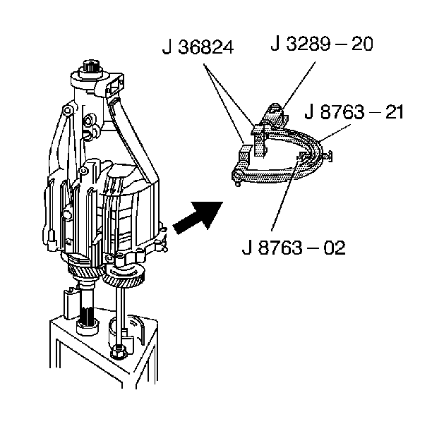
| • | J 3289-20 Base Holding Fixture |
| • | J 36509 Shift Shaft Detent Plug Remover |
| • | J 36515 Assembly Pallet |
| • | J 36515-15 Mainshaft Adapter |
| • | J 36515-16 Countershaft Adapter |
| • | J 36824 Transmission Adapters |
| • | J 8763-02 Holding Fixture C-Clamp |
| • | J 8763-21 Balance Bracket for C-Clamp |
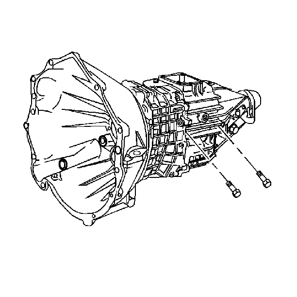
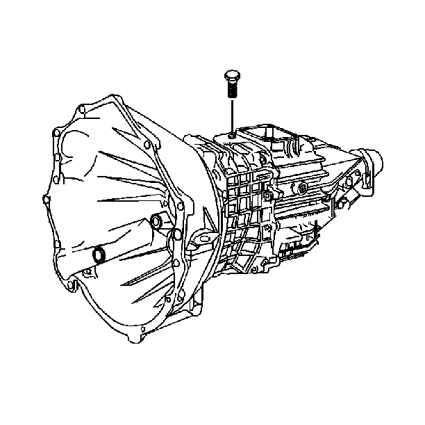
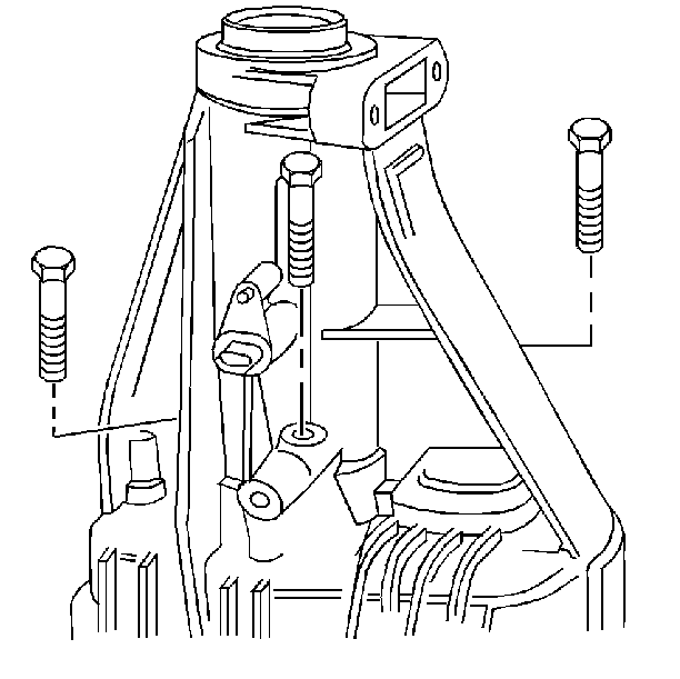
- Remove 2 reverse idler shaft support bolts.
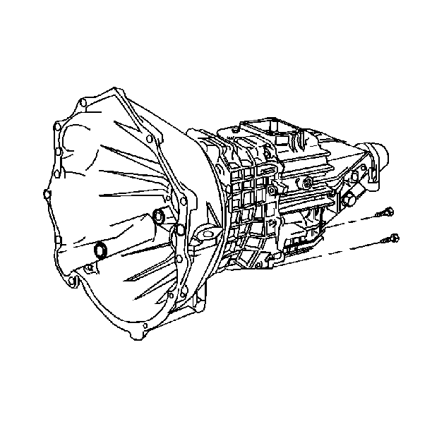
- Remove 2 lower-housing bolts. Tool J 3289-20 must be mounted securely on a sturdy workbench.
- Assemble the transmission holding fixture:
- Remove the backup lamp switch assembly.
- Remove the shift shaft block-out bushing pin.
- Remove the following components:
- Complete the following tasks:
- Remove the concentric slave cylinder.
- Position the transmission vertically. Scribe the retainer and the case to aid in ensuring proper position during reassembly. Remove the following components:
- Remove the retainer by screwing two of the removed bolts into the threaded holes provided. Press off the retainer.
- Tap the clutch release bearing pilot with a rubber mallet.
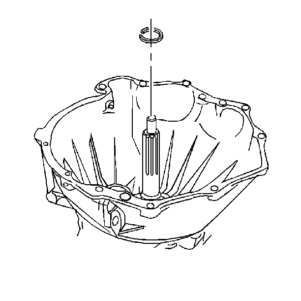
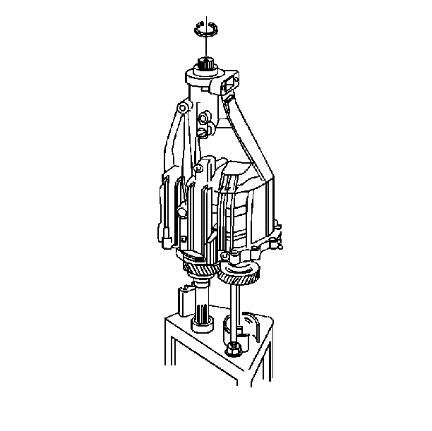
- Remove the input shaft snap ring.
- Position the transmission horizontally.
- Drive the 2 dowel pins into the front housing.
- Remove the front housing.
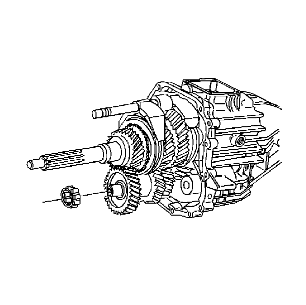
- Remove the countershaft bearing.
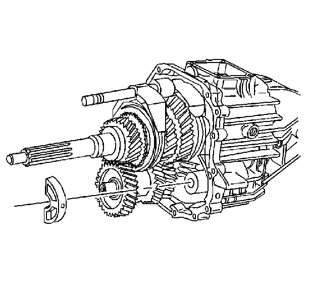
- Remove the reverse idler shaft support. The idler shaft support will snap out.
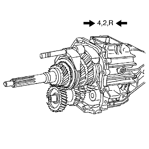
- Move all of the shift forks forward. Engage the 4th gear, the 2nd gear, and Reverse gear. Retain the shift lever detent plunger and spring.
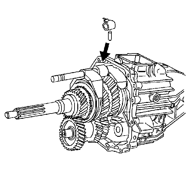
- Remove the shift shaft lever roll pin.
- Shift all of the gears into neutral.
- Engage the 5th speed gear.
- Push the shift shaft into the housing.
- Remove the shift shaft socket roll pin.
- Remove the following components:
- Remove the 3rd/4th speed gear shift fork. Rotate counterclockwise
- Loosen 3 bolts on the rear of the housing. Do not remove the bolts.
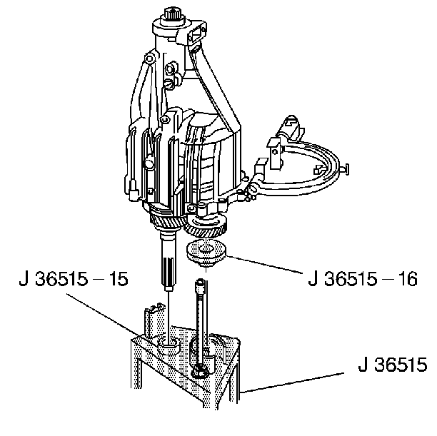
- Install the tool J 36515-15 on the input shaft.
- Install the tool J 36515-16 on the countershaft.
- Install the tool J 36515 to the transmission assembly.
- Place the unit fixture on the bench while holding the J 36515 fixture assembly on the transmission assembly.
- Remove tools J 8763-02 and J 36824 from the transmission housing.
- Remove the 3 bolts from the rear housing.
- Remove the rear housing. Tap the rear housing with a rubber mallet.
- Remove the mainshaft bearing retainer.
- Remove the following components:
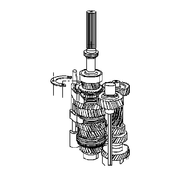
- Partially lift the mainshaft to allow removal of the countershaft. Remove the following components:
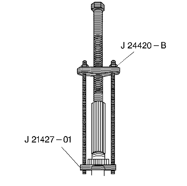
- Remove the vehicle speed sensor reluctor wheel. Use the J 21427-A and the J 24420-B . Discard the reluctor wheel.
- Remove the following components:
- Remove the mainshaft assembly from the assembly pallet J 36515 . Remove the following parts:
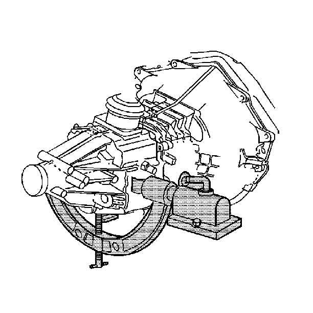
| 3.2. | The J 36824 onto the transmission housing |
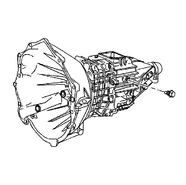
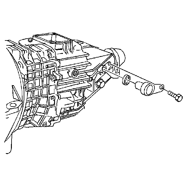
| 6.1. | The bolt |
| 6.2. | The vehicle speed sensor |
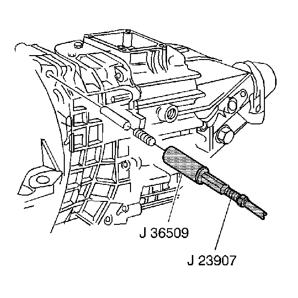
| 7.2. | Remove the detent spring and the detent plunger. |
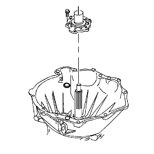
| 9.1. | The 6 bolts |
| 9.2. | The input shaft bearing retainer |
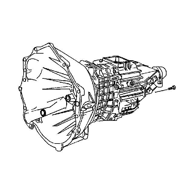
Remove the front housing to the rear housing bolts.
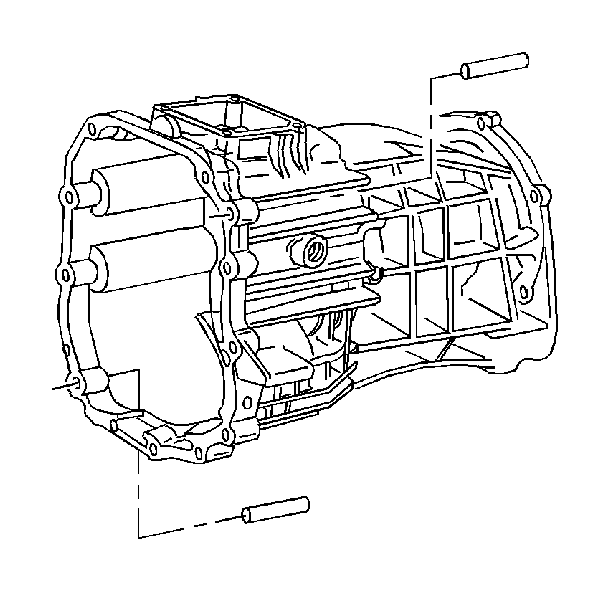
Important: Support the front housing. Do not allow the front housing to fall.
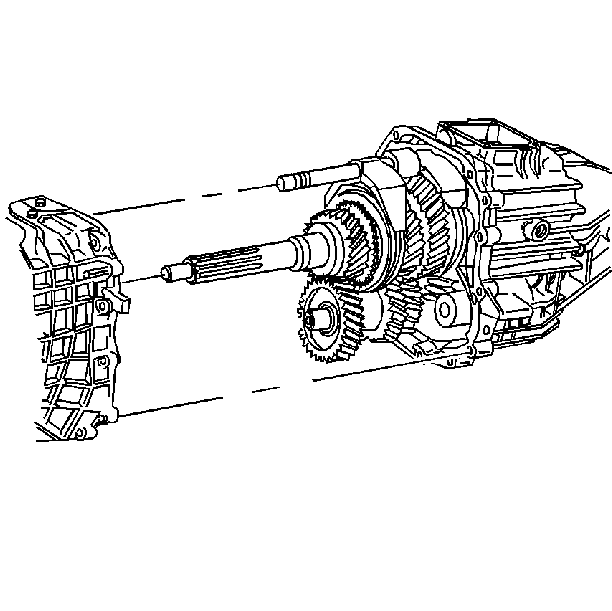
| 19.1. | Rotate the shift shaft lever finger down. |
| 19.2. | Support the shift shaft end. |
| 19.3. | Drive out the roll pin. |
| 19.4. | Ensure that the roll pin clears the 2nd speed gear. |
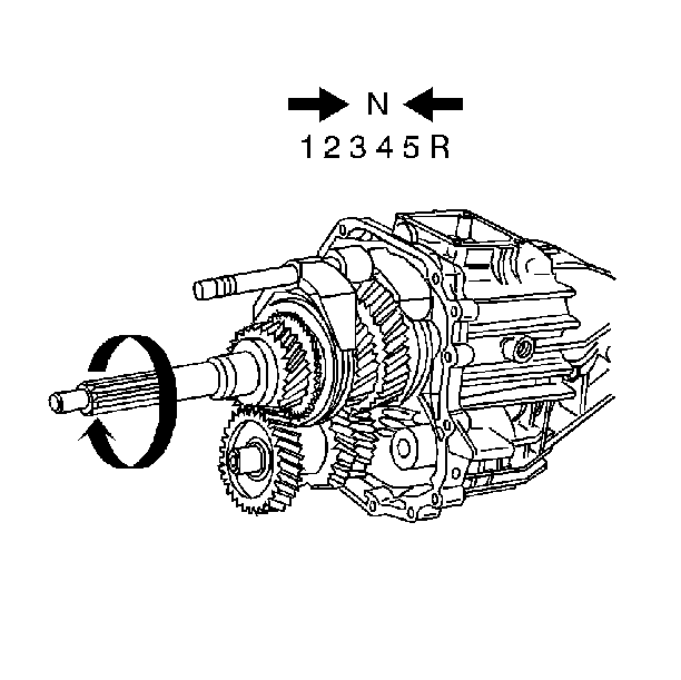
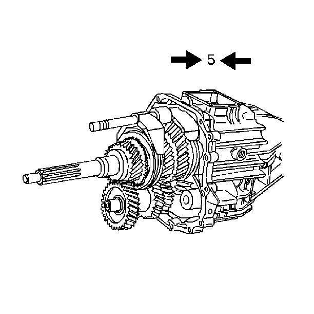
Notice: Excessive force peens the shift shaft and damages the shift shaft bearing. This causes increased shift effort.
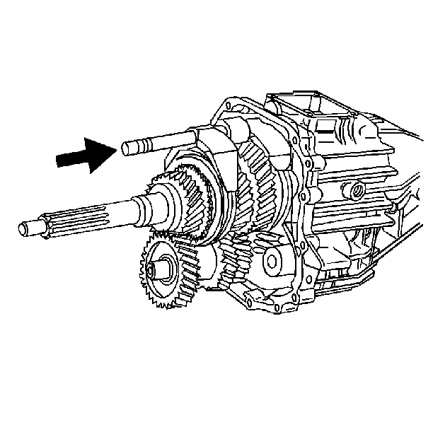
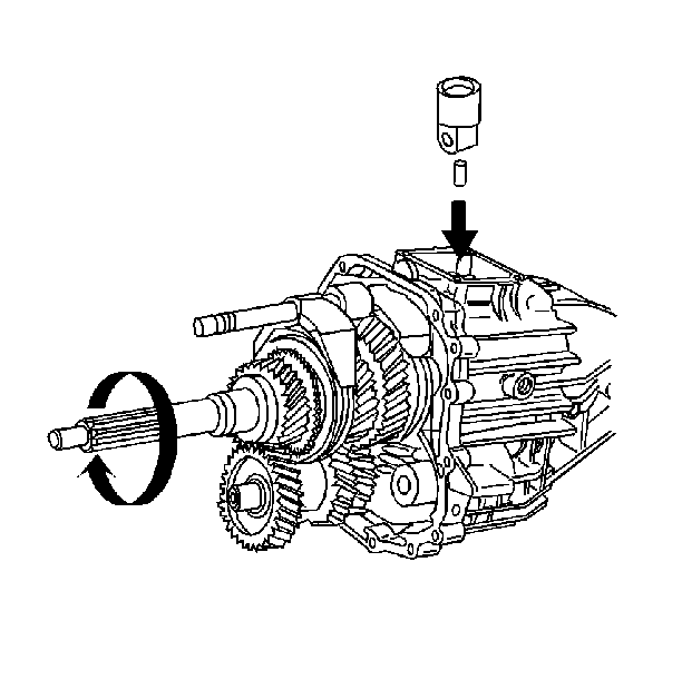
| 23.1. | Rotate the input shaft until a gap in the 5th speed/reverse speed synchronizer hub is directly under the roll pin. |
| 23.2. | Support the shift shaft end. |
| 23.3. | Drive out the roll pin. Use a 5 mm (3/16 in) punch. The roll pin will fall into the transmission housing. |
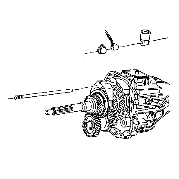
| 24.1. | The shift shaft |
| 24.2. | The shift shaft socket |
| 24.3. | The shift shaft lever |
| 24.4. | The shift shaft block-out bushing |
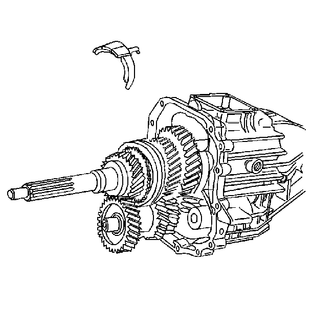
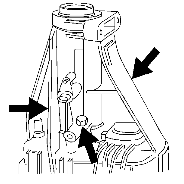
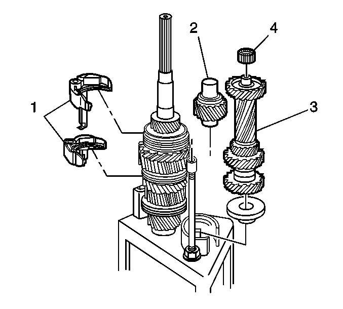
| 35.1. | 2 shift forks (1) |
| 35.2. | The reverse idler gear (2) |
| 36.1. | The countershaft (3) |
| 36.2. | The countershaft bearing (4) |
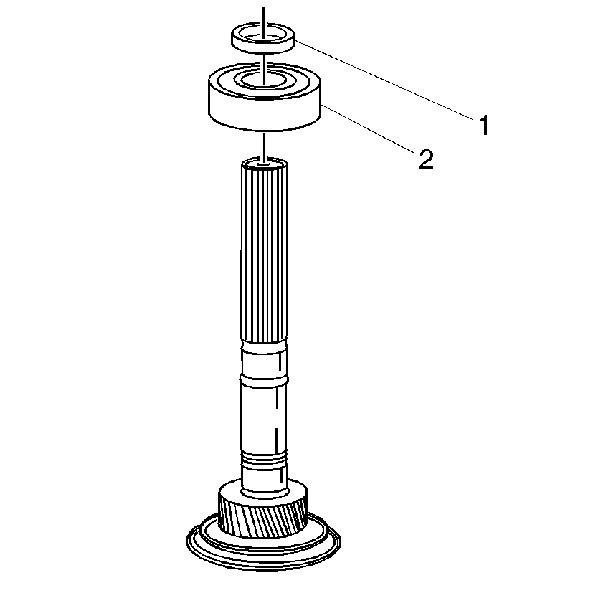
| • | The rear mainshaft bearing snap ring (1) |
| • | The rear mainshaft bearing (2) |
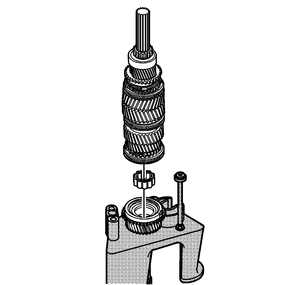
| • | The input shaft |
| • | The mainshaft pilot bearing from the input shaft |
Transmission Disassemble Two Wheel Drive
Transmission Disassembly
Tools Required
| • | J 21427-A Speedometer Gear Puller Adapter |
| • | J 23907 Slide Hammer |
| • | J 24420-B Gear Puller |
| • | J 26941 Output Shaft Oil Seal Remover |
| • | J 3289-20 Base Holding Fixture |
| • | J 36509 Shift Shaft Detent Plug Remover |
| • | J 36515 Assembly Pallet |
| • | J 36515-15 Mainshaft Adapter |
| • | J 36515-16 Countershaft Adapter |
| • | J 36824 Transmission Adapters |
| • | J 8763-02 Holding Fixture C-Clamp |
| • | J 8763-21 Balance Bracket for C-Clamp |
- Remove 2 reverse idler shaft support bolts.
- Remove 2 lower-housing bolts. Tool J 3289-20 must be mounted securely on a sturdy workbench.
- Assemble the transmission holding fixture:
- Remove the backup lamp switch assembly.
- Remove the shift shaft block-out bushing pin.
- Remove the following components:
- Complete the following tasks:
- Remove the concentric slave cylinder.
- Position the transmission vertically. Scribe the retainer and the case to aid in ensuring proper position during reassembly. Remove the following components:
- Remove the retainer by screwing two of the removed bolts into the threaded holes provided. Press off the retainer.
- Tap the clutch release bearing pilot with a rubber mallet.
- Remove the input shaft snap ring.
- Position the transmission horizontally.
- Drive the 2 dowel pins into the front housing.
- Remove the front housing.
- Remove the countershaft bearing.
- Remove the reverse idler shaft support. The idler shaft support will snap out.
- Move all of the shift forks forward. Engage the 4th gear, the 2nd gear, and Reverse gear. Retain the shift lever detent plunger and spring.
- Remove the shift shaft lever roll pin.
- Shift all of the gears into neutral.
- Engage the 5th speed gear.
- Push the shift shaft into the housing.
- Remove the shift shaft socket roll pin.
- Remove the following components:
- Remove the 3rd/4th speed gear shift fork. Rotate counterclockwise
- Loosen 3 bolts on the rear of the housing. Do not remove the bolts.
- Install the tool J 36515-15 on the input shaft.
- Install the tool J 36515-16 on the countershaft.
- Install the tool J 36515 to the transmission assembly.
- Place the unit fixture on the bench while holding the J 36515 fixture assembly on the transmission assembly.
- Remove tools J 8763-02 and J 36824 from the transmission housing.
- Remove the 3 bolts from the rear housing.
- Remove the rear housing. Tap the rear housing with a rubber mallet.
- Remove the mainshaft bearing retainer.
- Remove the following components:
- Partially lift the mainshaft to allow removal of the countershaft. Remove the following components:
- Remove the vehicle speed sensor reluctor wheel. Use the J 21427-A and the J 24420-B . Discard the reluctor wheel.
- Remove the following components:
- Remove the mainshaft assembly from the assembly pallet J 36515 . Remove the following parts:


| 3.2. | The J 36824 onto the transmission housing |


| 6.1. | The bolt |
| 6.2. | The vehicle speed sensor |

| 7.2. | Remove the detent spring and the detent plunger. |

| 9.1. | The 6 bolts |
| 9.2. | The input shaft bearing retainer |


Remove the front housing to the rear housing bolts.

Important: Support the front housing. Do not allow the front housing to fall.


| 19.1. | Rotate the shift shaft lever finger down. |
| 19.2. | Support the shift shaft end. |
| 19.3. | Drive out the roll pin. |
| 19.4. | Ensure that the roll pin clears the 2nd speed gear. |


Notice: Excessive force peens the shift shaft and damages the shift shaft bearing. This causes increased shift effort.


| 23.1. | Rotate the input shaft until a gap in the 5th speed/reverse speed synchronizer hub is directly under the roll pin. |
| 23.2. | Support the shift shaft end. |
| 23.3. | Drive out the roll pin. Use a 5 mm (3/16 in) punch. The roll pin will fall into the transmission housing. |

| 24.1. | The shift shaft |
| 24.2. | The shift shaft socket |
| 24.3. | The shift shaft lever |
| 24.4. | The shift shaft block-out bushing |


| 35.1. | 2 shift forks (1) |
| 35.2. | The reverse idler gear (2) |
| 36.1. | The countershaft (3) |
| 36.2. | The countershaft bearing (4) |


| • | The rear mainshaft bearing snap ring (1) |
| • | The rear mainshaft bearing (2) |

| • | The input shaft |
| • | The mainshaft pilot bearing from the input shaft |
Transmission Disassemble Four Wheel Drive
Transmission Disassembly
Tools Required
| • | J 23907 Slide Hammer with Pilot Bearing Puller |
| • | J 3289-20 Base Holding Fixture |
| • | J 36509 Detent Spring Plug Remover |
| • | J 36515 Assembly Pallet |
| • | J 36515-15 Mainshaft Adapter |
| • | J 36515-16 Countershaft Adapter |
| • | J 36824 Transmission Adapters |
| • | J 36825 4WD Output Shaft Oil Seal Remover |
| • | J 8763-02 Holding Fixture C-Clamp |
| • | J 8763-21 Balance Bracket for C-Clamp |
- Remove the two reverse idler shaft support bolts
- Remove two housing bolts
- Assemble the transmission holding fixture:
- Remove the backup lamp switch assembly.
- Remove the shift shaft block-out bushing pin.
- Remove the following components:
- Remove the output shaft oil seal. Use J 36825 and J 23907 .
- Position the transmission vertically. Remove the following components:
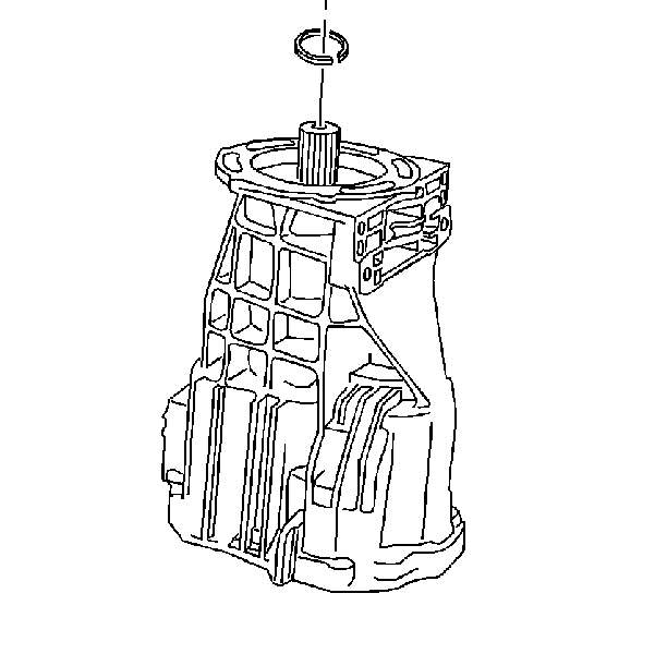
- Remove the input shaft snap ring.
- Position the transmission horizontally. Remove the front housing to the rear housing bolts.
- Drive the 2 dowel pins into the front housing.
- Remove the front housing.
- Remove the countershaft bearing.
- Remove the reverse idler shaft support. The idler shaft support will snap out.
- Move all the shift forks forward. Engage 4th gear, 2nd gear, and Reverse gear. Retain the shift lever detent plunger and spring.
- Remove the shift shaft lever roll pin.
- Shift all the gears into neutral.
- Engage the 5th speed gear.
- Push the shift shaft into the housing.
- Remove the shift shaft socket roll pin.
- Remove the following components:
- Remove the 3rd/4th speed gear shift fork. Rotate counterclockwise
- Install tool J 36515-15 on the input shaft.
- Install tool J 36515-16 on the countershaft.
- Install J 36515 to the transmission assembly with the adapters and transmission assembly upright on the work bench.
- Remove J 8763-02 and J 36824 from the transmission housing.
- Remove the mainshaft bearing snap ring.
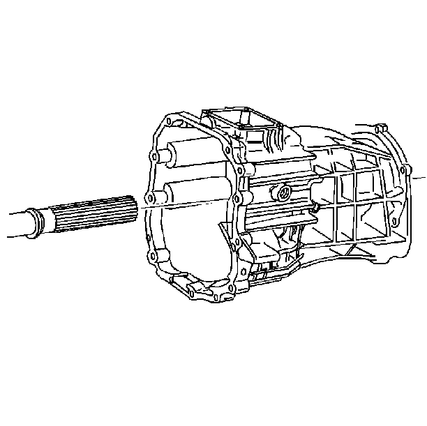
- Remove the rear housing. Tap the rear housing with a rubber mallet.
- Remove the following components:
- Remove the mainshaft assembly from the assembly pallet J 36515 . Remove the following parts:


| 3.2. | J 36824 onto the transmission housing |
| 3.5. | Mount tool J 3289-20 securely on a sturdy workbench. |


| 6.2. | The detent spring |
| 6.3. | The detent plunger |
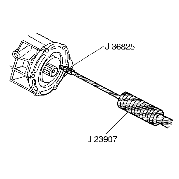
Use J 36825 by screwing it into one of the three perforated holes in the seal.

| 8.1. | The 6 bolts |
| 8.2. | The input shaft bearing retainer |
| 8.3. | Tap the clutch release bearing pilot with a rubber mallet. |


| 16.1. | Rotate the shift shaft lever finger down. |
| 16.2. | Support the shift shaft end. |
| 16.3. | Drive out the roll pin. |
| 16.4. | Ensure the roll pin clears the 2nd speed gear. |


Notice: Excessive force peens the shift shaft and damages the shift shaft bearing. This causes increased shift effort.


| 20.1. | Rotate the input shaft until a gap in the 5th speed/reverse speed synchronizer hub is directly under the roll pin. |
| 20.2. | Support the shift shaft end. |
| 20.3. | Drive out the roll pin. Use a 5 mm (3/16 in) punch. |
| 20.4. | The roll pin will fall into the transmission housing. |

| 21.1. | The shift shaft |
| 21.2. | The shift shaft socket |
| 21.3. | The shift shaft lever |
| 21.4. | The shift shaft block-out bushing |



| 29.1. | Two shift forks (1) |
| 29.2. | The reverse idler gear (2) |
| 29.3. | The countershaft (3) |
| 29.4. | The countershaft bearing (4) |

| • | The input shaft |
| • | The mainshaft pilot bearing from the input shaft |
