Tools Required
- Raise and support the vehicle.
- Support the axle using a suitable portable safety stand.
- Remove both brake drums.

- Remove the axle cover
bolts, the cover and the gasket. Drain the axle lubricant.
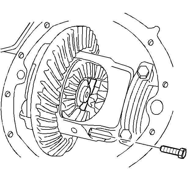
- Remove the pinion shaft
lock bolt.
- Remove the pinion shaft.
| • | Push the axle shaft in towards the center of the differential
case. |
| • | Remove the C lock from the end of the axle shaft. |
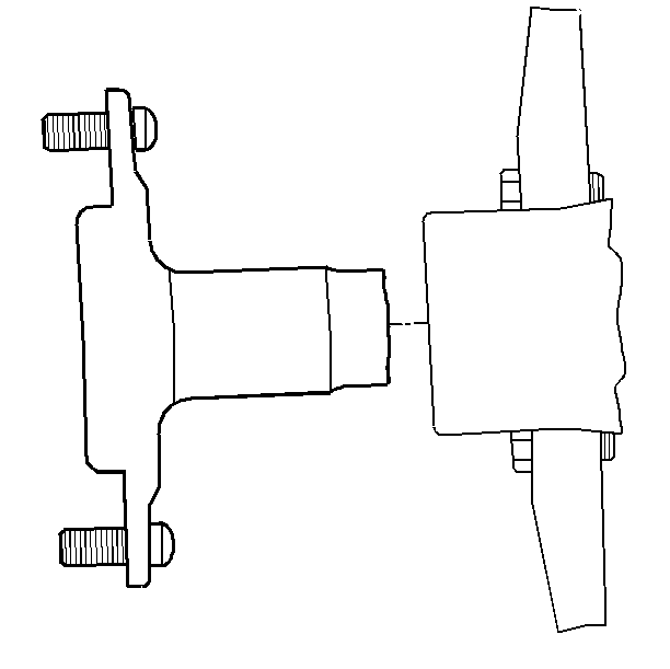
- Remove the axle shaft
from the axle housing.
- Remove the oil seal using a seal removal tool. Do not damage the
housing.
Important: The jaws of the tool must engage the bearing outer race.
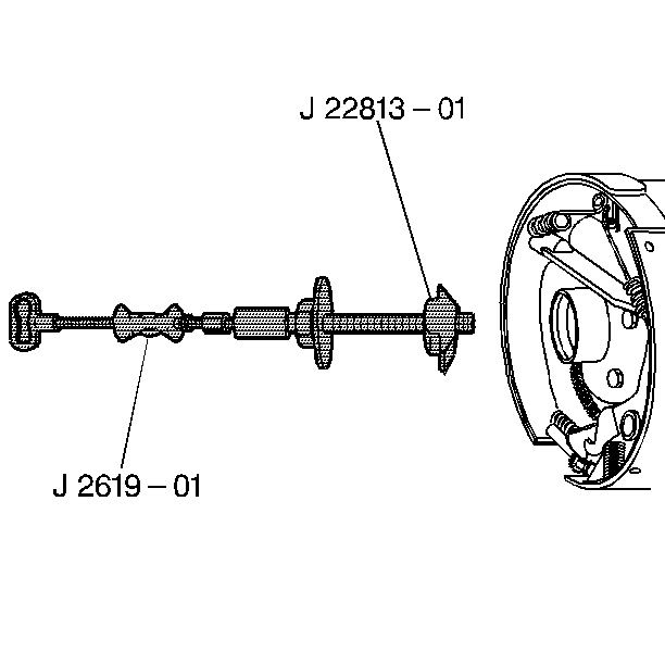
- Remove the bearing, using
the J 2619-O1
and the J 22813-A
.
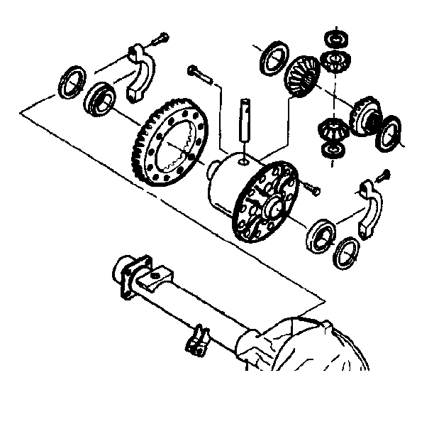
- Remove the differential
pinion and the side gears.
- Roll the pinion gears out of the case with the pinion thrust washers.
- Mark the gears and the differential case LEFT and RIGHT when removing
the side gears and the side gear thrust washers.
- Remove the bearing caps and bolts. Mark the caps and the housing
LEFT and RIGHT.
Notice: When removing the differential case from the axle housing, do not damage
the cover gasket surface. If the cover gasket surface is damaged, lubricant
may leak from the axle and cause premature failure of the axle assembly.
- Remove the differential case.
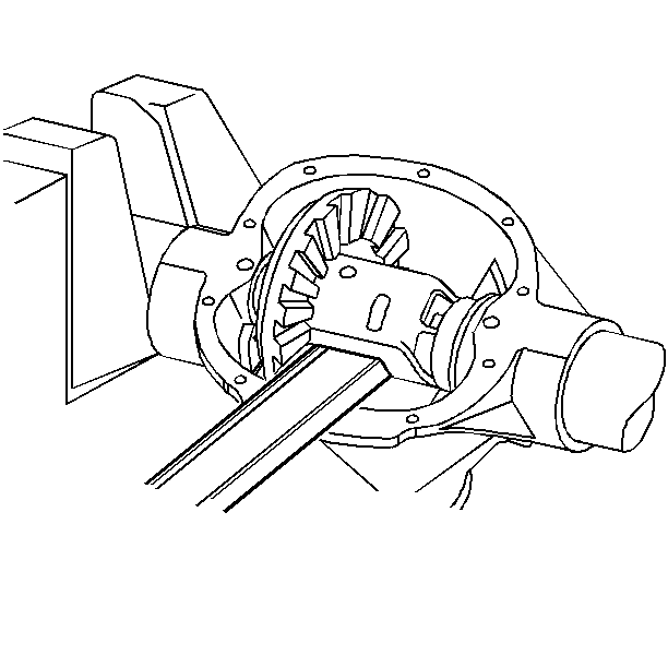
- Pry the case from the
axle housing at the differential window.
- Remove the bearing outer races, the shims, and the spacers.
- Mark the races and shims LEFT and RIGHT. Place the races and the
shims with the bearing caps.
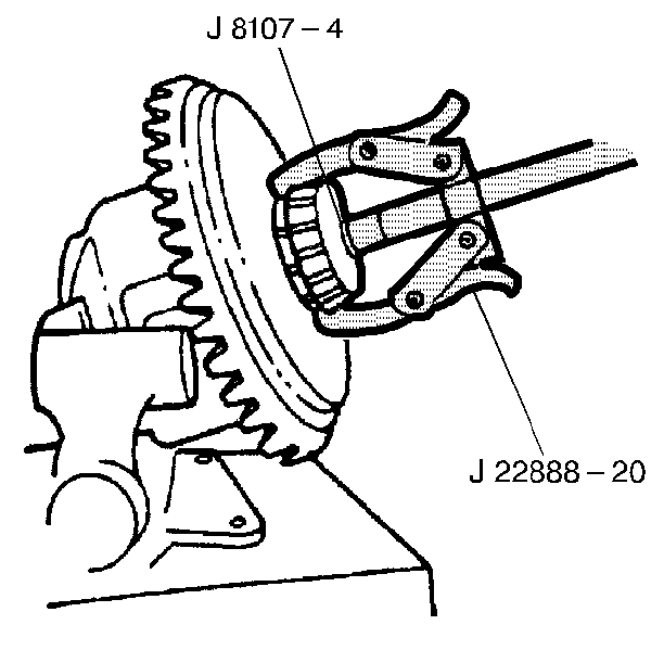
Important: The jaws of the J 22888-20A
must pull from beneath the bearing cone and not the cage.
- Remove the differential side bearings, using theJ 8107-4
and theJ 22888-20A
.
- Remove the left handed threaded ring gear bolts.
Notice: Do not pry the ring gear from the case. This will damage the ring gear
and differential case.
- Remove the ring gear from the differential. Drive the gear off using
a brass drift if necessary.
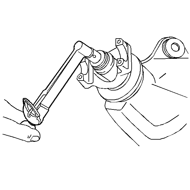
- Inspect the differential
drive pinion bearing preload.
| • | If there is no reading, inspect the drive pinion gear for looseness
by shaking the gear. |
| • | When operating the rear axle for an extended period of time with
loose bearings or a worn yoke, you will need to replace the ring and pinion
gear. |
- Inspect the pinion assembly for looseness by moving the pinion
back and forth. Looseness indicates excessive bearing wear.
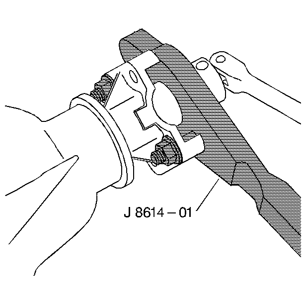
- Remove the pinion flange
nut and washer using the J 8614-01
in order to hold the pinion flange.
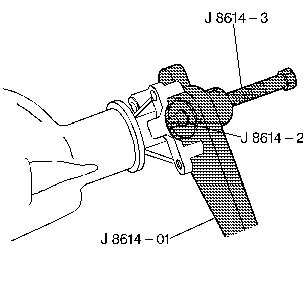
- Remove the pinion flange
using the J 8614-01
.
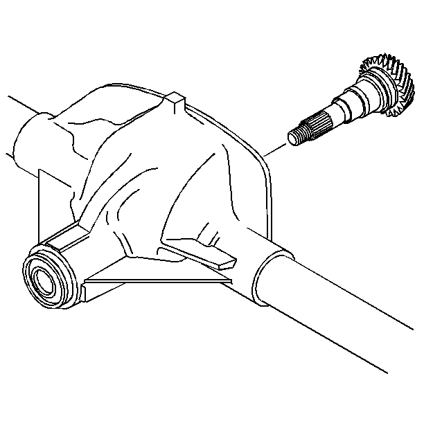
- Remove the pinion from
the axle housing.
| • | Thread the pinion nut halfway onto the pinion. |
| • | Install the differential cover with two bolts in order to prevent
the pinion from falling. |
| • | Drive the pinion out of the housing using a hammer and a drift. |
| • | Remove the pinion and cover. |
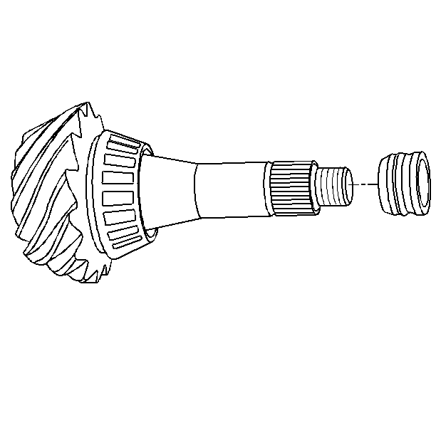
- Remove the collapsible
spacer from the pinion. Discard the spacer.
- Remove the outer seal, using a seal removal tool, and the outer
pinion bearing.
- Remove the inner bearing and the shim from the pinion.
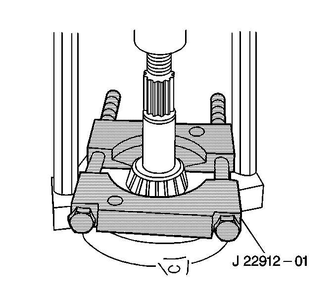
- Press the bearing off
of the pinion using theJ 22912-B
.
- Remove the shim.
- Remove the drive pinion bearing cups from the axle housing using
a hammer and punch in the slots provided. Move the punch back and forth between
one side of the cup and the other in order to work the cups out of the
housing evenly.


