For 1990-2009 cars only
Tools Required
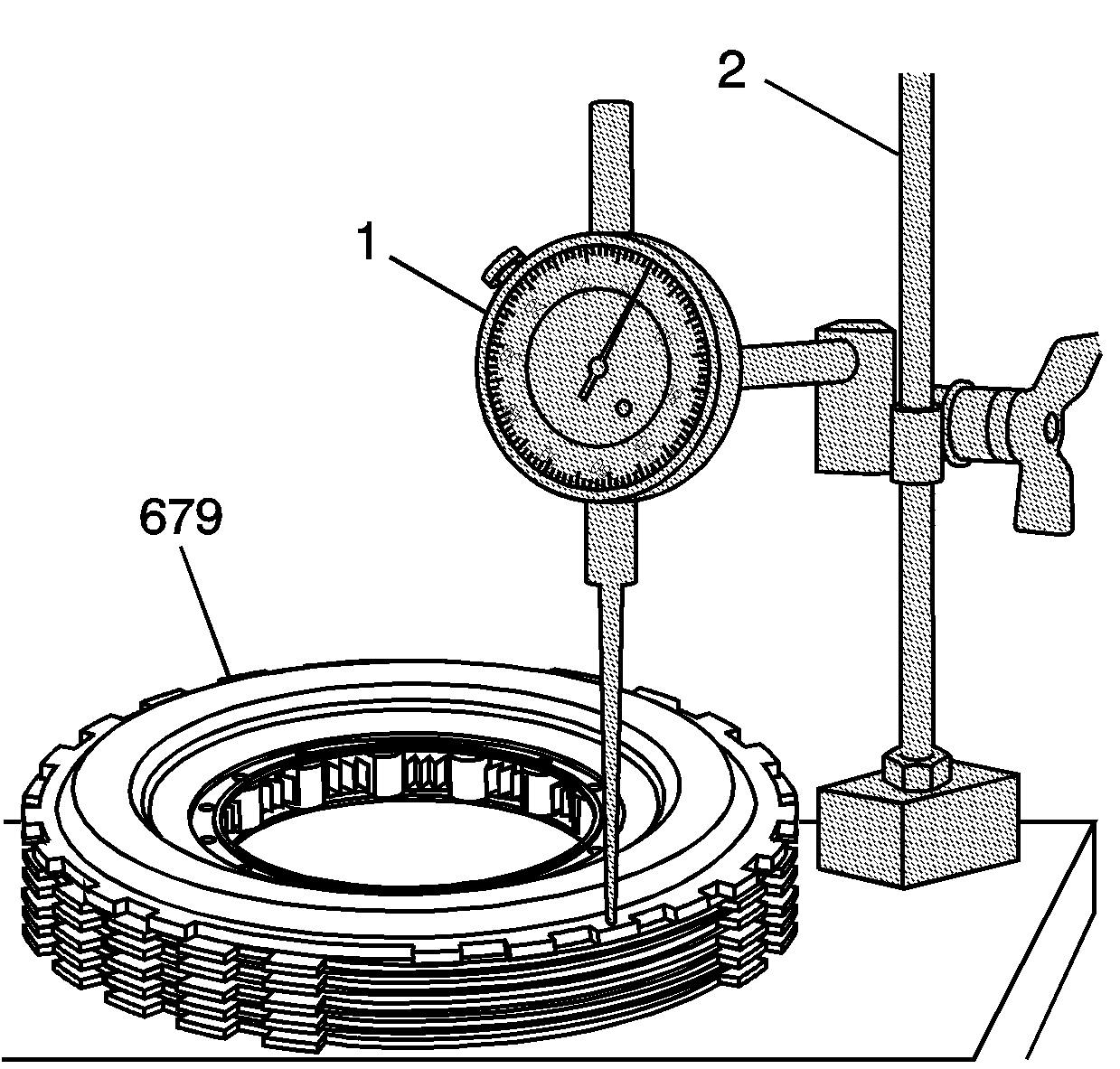
| • | J 8001 Dial Indicator Set |
| • | J 26900-13 Magnetic Indicator Base |
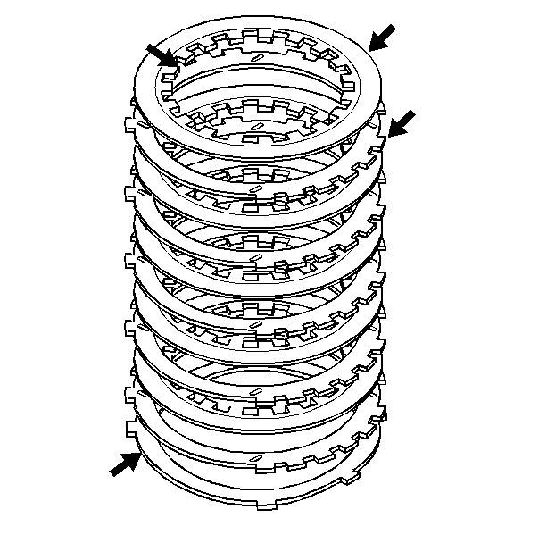
- Inspect the low and reverse clutch plates for the following conditions:
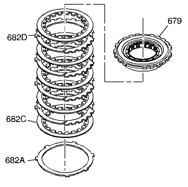
- Stack the low and reverse clutch plate assembly on a flat surface in the following order:
- Using the J 8001 and the J 26900-13 , measure the height of the clutch pack from the work surface to the top of the low and reverse clutch support.
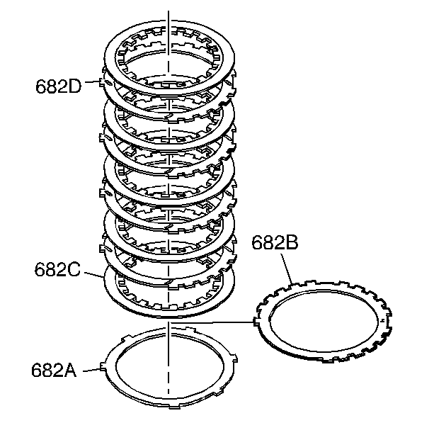
- Refer to Low and Reverse Clutch Spacer Plate Selection in order to select the proper thickness of the low and reverse clutch selective spacer plate (682B).
- Install the proper selective spacer plate (682B) between the wave plate (682A) and the first fiber plate assembly (682C), with the identification side up.

| • | Composition material wear |
| • | Composition material heat damage |
| • | Composition material delamination |
| • | Steel plates heat damage |
| • | Steel plates surface finish damage |

| 2.1. | One waved plate (682A) |
| 2.2. | Five fiber plate assemblies (682C) and four steel plates (682D), starting with one fiber plate assembly and alternating with steel |
| 2.3. | Low and reverse clutch support (679) |


The overall height for the clutch pack including the selective spacer plate should be 29.22-29.90 mm (1.15-1.18 in).
