GM Service Manual Online
For 1990-2009 cars only
Makes
🢒
Isuzu
🢒
1999
🢒
S/T Isuzu - 4WD
🢒
Body and Accessories
🢒
Wiring Systems
🢒 Data Link Connector Schematics
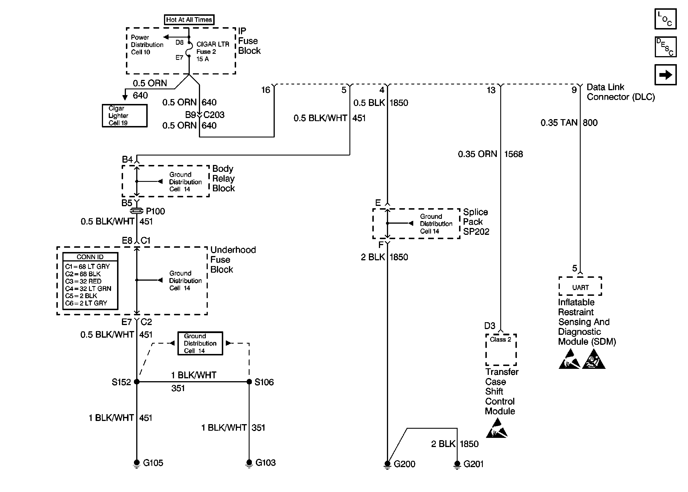
Figure
1:
Cell 50: Power, Ground and SRS
Cell 10: INT BATT, PWR LKS, CTSY LP and CIGAR LTR Fuses
Cell 19
Cell 14: Underhood Grounds
Power and Grounding Connector End Views
Cell 14: Underhood Grounds
Cell 14: G103 and G105 (4.3L)
Handling ESD Sensitive Parts Notice
SRS Service Precautions
Data Link Communications Components
Data Link Communications Circuit Description
Cell 50: SP201 (2.2L)
Cell 14: G200, G201 and G207
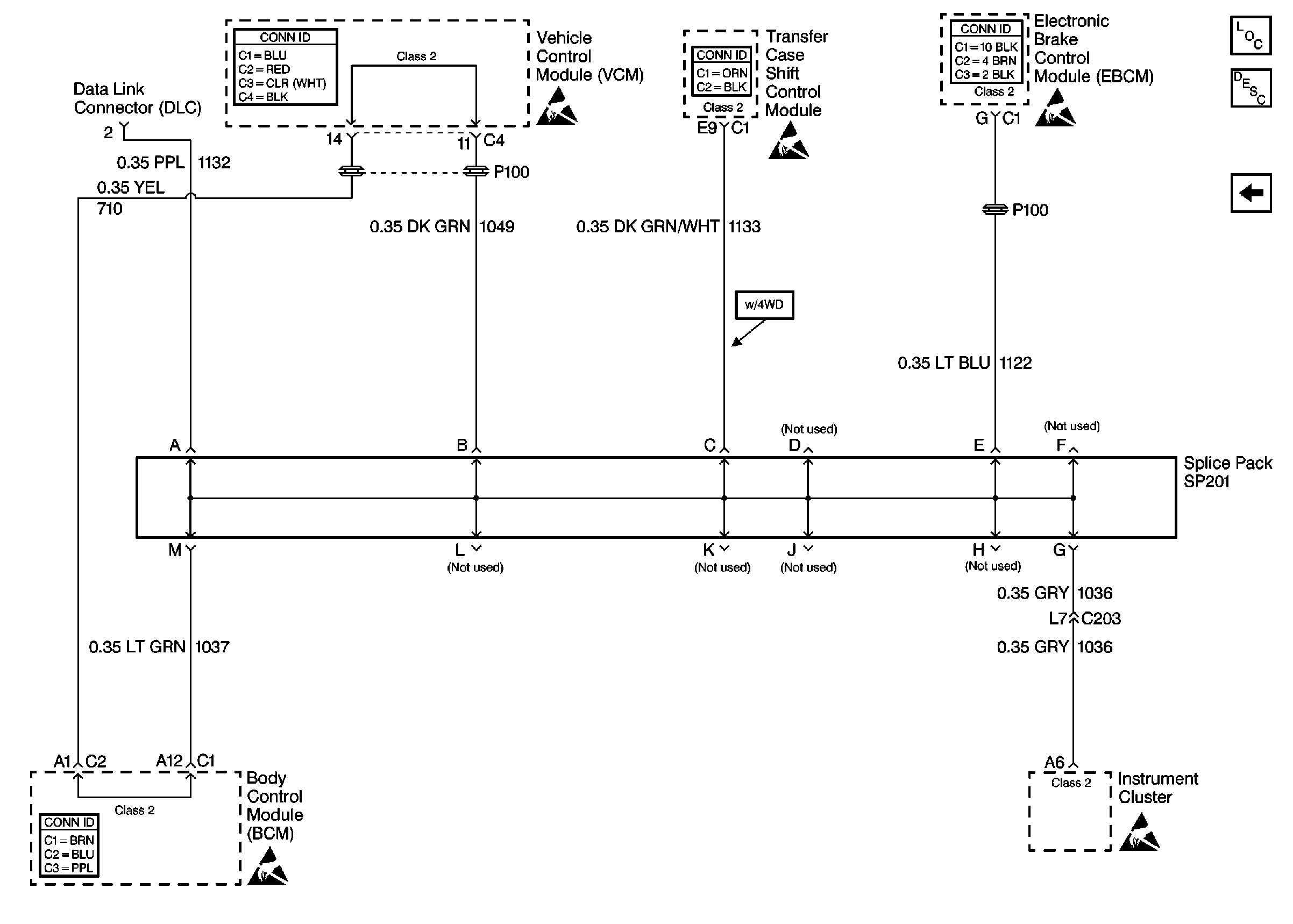
Figure
2:
Cell 50: SP201 (2.2L)
Powertrain Control Module Connector End Views
Handling ESD Sensitive Parts Notice
Antilock Brake System Connector End Views
Data Link Communications Components
Data Link Communications Circuit Description
Cell 50: SP201 (4.3L)
Cell 50: Power, Ground and SRS
Body Control System Connector End Views
Handling ESD Sensitive Parts Notice
Figure
3:
Cell 50: SP201 (4.3L)
VCM Connector End Views
Handling ESD Sensitive Parts Notice
Transfer Case Control Connector End Views
Handling ESD Sensitive Parts Notice
Antilock Brake System Connector End Views
Handling ESD Sensitive Parts Notice
Data Link Communications Components
Data Link Communications Circuit Description
Cell 50: SP201 (2.2L)
Body Control System Connector End Views
Handling ESD Sensitive Parts Notice