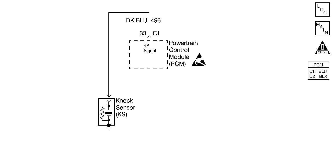
Circuit Description
The knock sensor (KS) system detects for an engine detonation. The knock sensor produces an AC voltage signal. The amplitude and the frequency of the AC voltage signal is dependent upon the knock level being detected. This signal then travels to the KS module that is an internal part of the powertrain control module (PCM). If knock is detected, the PCM will retard the spark timing based on the signal from the knock sensor.
Conditions for Running the DTC
| • | Engine run time is more than 20 seconds. |
| • | Engine coolant temperature (ECT) is more than 56°C (131°F). |
| • | Engine speed is above 1,600 RPM. |
| • | MAP is more than 60 kPa. |
Conditions for Setting the DTC
| • | The KS voltage and variation is not within normally expected ranges. |
| • | The above conditions are present for more than 60 seconds. |
Action Taken When the DTC Sets
| • | The control module illuminates the malfunction indicator lamp (MIL) if a failure is detected during 2 consecutive key cycles. |
| • | The control module sets the DTC and records the operating conditions at the time the diagnostic failed. The failure information is stored in the scan tool Freeze Frame and Failure Records. |
Conditions for Clearing the MIL/DTC
| • | The control module turns OFF the MIL after 3 consecutive drive trips when the test has run and passed. |
| • | A history DTC will clear if no fault conditions have been detected for 40 warm-up cycles (coolant temperature has risen 22°C (40°F) from the startup coolant temperature and the engine coolant temperature is more than 70°C (158°F) during the same ignition cycle). |
| • | Use a scan tool to clear the DTCs. |
Diagnostic Aids
| • | Listen for and correct any abnormal engine noise before using the diagnostic table. |
| • | Thoroughly inspect any suspected circuitry for the following conditions: |
| - | Backed out terminals |
| - | Improper mating |
| - | Broken locks |
| - | Improperly formed connectors |
| - | Damaged terminals |
| - | Poor terminal to wiring connections |
| - | Physical damage to the wiring harness |
Test Description
The numbers below refer to the step numbers on the diagnostic table:
-
This step verifies if the code is current or intermittent.
-
If the engine has an internal knock or an audible noise that causes a knocking type noise on the engine block, this is an indication that the knock sensor may be responding to the noise.
-
This step tests the internal resistance of the knock sensor or the wiring to the knock sensor.
-
The replacement PCM must be programmed and the Crankshaft Position System Variation Learn procedure must be performed.
Step | Action | Values | Yes | No | ||||||
|---|---|---|---|---|---|---|---|---|---|---|
1 | Did you perform the Powertrain On-Board Diagnostic (OBD) System Check? | -- | ||||||||
Does the DTC reset? | -- | Go to Diagnostic Aid | ||||||||
Listen to the engine while raising and lowering the engine speed. Is a knock or audible noise present? | -- | |||||||||
4 |
Did you find and correct the condition? | -- | Go to Diagnostic Aid | |||||||
Does the resistance measure within the specified value? | 90-110 ohms | |||||||||
6 |
Did you find and correct the condition? | -- | ||||||||
|
Important:: The replacement PCM must be programmed. Replace the PCM. Refer to Powertrain Control Module Replacement/Programming . Did you complete the replacement? | -- | -- | ||||||||
8 |
Did you find and correct the condition? | -- | ||||||||
9 |
Did you find and correct the condition? | -- | ||||||||
10 | Replace the knock sensor (KS). Refer to Knock Sensor Replacement . Did you complete the replacement? | -- | -- | |||||||
11 |
Does the DTC reset? | -- | System OK |
