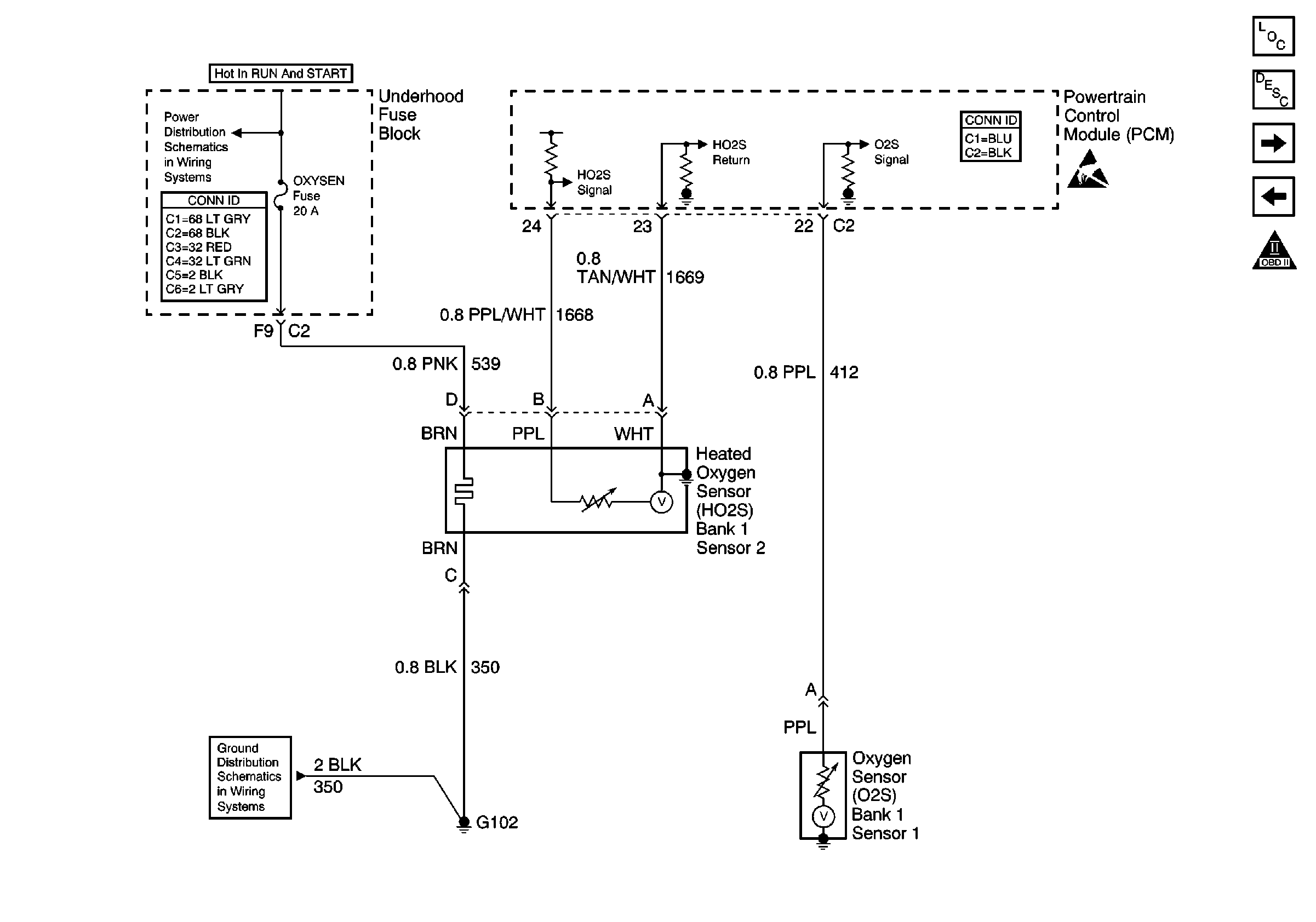
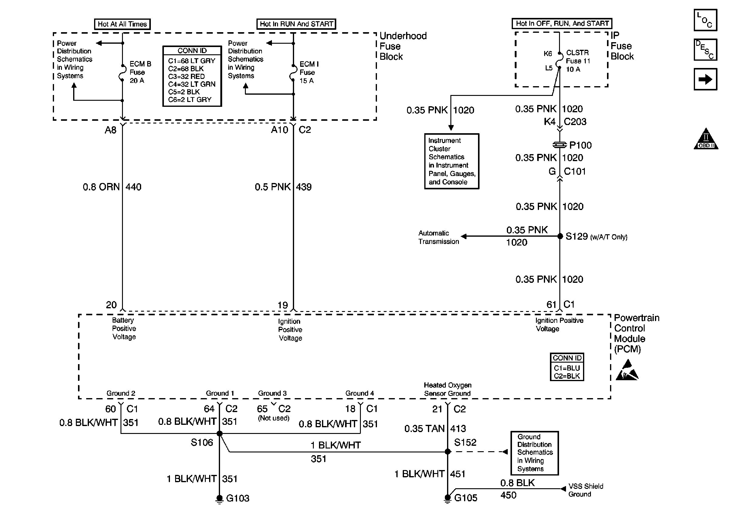
Refer to
Oxygen Sensors

and
Power and Grounding

Circuit Description
A three-way catalytic converter is used in order to control the exhaust
emissions of hydrocarbons (HC), carbon monoxide (CO) and oxides of nitrogen
(NOx). The catalyst within the converter promotes a chemical reaction
which oxidizes the HC and the CO that is present in the exhaust
gas. This will convert the HC and the CO into a harmless water vapor
and a carbon dioxide, and reduces the NOx, converting the NOx into
nitrogen. The catalytic converter also has the ability to store
oxygen. The powertrain control module (PCM) has the capability to monitor
this process by using a heated oxygen sensor (HO2S) which is in
the exhaust stream past the three-way catalytic converter. The HO2S
produces an output signal which indicates the oxygen storage capacity
of the catalyst. This in turn indicates the catalysts ability to
convert the exhaust emissions effectively. The PCM monitors the catalyst
efficiency by first allowing the catalyst to heat up, waiting for
a stabilization period while the engine is idling. Then, the PCM
adds and removes the fuel while monitoring the reaction of the HO2S.
When the catalyst is functioning properly, the HO2S 2 response
to the extra fuel is slow compared to the O2S 1. When the HO2S 2
response is close to that of the O2S 1, the oxygen storage
capability or efficiency of the catalyst is considered to be bad,
and the MIL will illuminate.
Conditions for Running the DTC
| • | No active oxygen sensor DTCs |
| • | No active fuel trim DTCs |
| • | No active injector control DTCs |
| • | No active fuel tank pressure DTCs |
| • | No active CKP system variation not learned DTCs |
| • | The engine has been running longer than 510 seconds after
the throttle has moved |
| • | The BARO is above 72 kPa |
| • | The vehicle is in a Closed Loop operation |
| • | The vehicle has been driven above 1,200 RPM for more than
36 seconds since last idle period |
| • | Battery voltage is more than 9 volts |
Then, with the vehicle stopped:
| • | Engine is idling less than 150 RPM from the desired idle. |
| • | The vehicle is in drive (automatic) or neutral (manual). |
| • | The throttle position (TP) is 0 percent. |
| • | The engine coolant temperature (ECT) is between 75°C (167°F)
and 125°C (257°F). |
| • | The intake air temperature (IAT) is between -20°C (-4°F)
and 80°C (176°F). |
| • | The Short Term FT is between 93 (-28 percent) and
163 (+28 percent). |
| • | The catalytic temperature is above 510°C (950°F)
for 2.4L or 345°C (653°F) for 2.2L. In order to obtain the
correct temperature to run the test, drive the vehicle until
the converter temperature is 50°C (122°F) above the
condition for running the DTC. |
| • | The above conditions are present for up to 30 seconds. |
Conditions for Setting the DTC
The HO2S 2 response is too quick.
Action Taken When the DTC Sets
| • | The malfunction indicator lamp (MIL) will illuminate. |
| • | The PCM will record the operating conditions at the time that
the diagnostic fails. The Freeze Frame and Failure Records buffers will store
this information. |
Conditions for Clearing the MIL/DTC
| • | The MIL will turn off after 3 consecutive ignition cycles
in which the diagnostic runs without a fault. |
| • | A history DTC will clear after 40 consecutive warm up cycles
without a fault. |
| • | Use a scan tool to clear the DTCs. |
Diagnostic Aids
| • | An intermittent problem may be caused by the following conditions: |
| - | Rubbed through wire insulation |
| - | A broken wire inside the insulation |
| • | Any circuitry that is suspected of causing the intermittent complaint
should be thoroughly inspected for the following conditions: |
| - | Physical damage to the wiring harness |
Test Description
The numbers below refer to the step numbers on the diagnostic table:
-
If any component
DTCs are set, diagnose those DTCs first. A malfunction in a component can
cause the converter to appear degraded or may have caused
the malfunction.
-
This step includes
checks for conditions that can cause the three-way catalytic converter
to appear degraded. Repair any problems found before proceeding
with this table.
-
If you need
to replace the three-way catalytic converter, make sure that another condition
is not present which may cause damage to the converter.
Correct any possible causes of converter damage before
replacing the catalytic converter in order to avoid damage
to the replacement converter.
These conditions may include the following items:
| • | High engine oil or coolant consumption |


