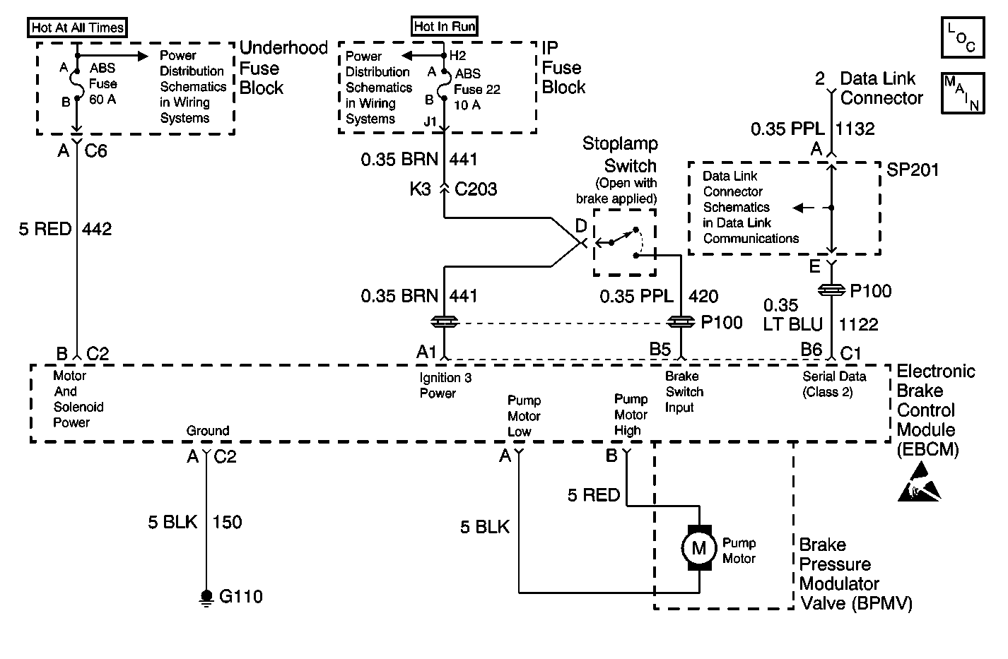
Circuit Description
The ABS Diagnostic System Check is an organized approach to identify problems associated with the EBCM. This check must be the starting point for any EBCM complaint, and will direct you to the next logical step in diagnosing the complaint. The EBCM is a very reliable component and is not likely the cause of the malfunction. Most system complaints are linked to faulty wiring, connectors, and occasionally to components. Understanding the ABS system and using the tables correctly will reduce diagnostic time and prevent unnecessary parts replacement.
Diagnostic serial data is transmitted/received by the EBCM through connector C1, terminal B6. The EBCM is supplied battery voltage through connector C2, terminal B and switched ignition voltage through connector C1, terminal A1. Ground is provided through connector C2, terminal A.
Diagnostic Aids
Excessive resistance in the ground or power supply circuits will not allow communication with the EBCM. If communication with the EBCM is not possible, ensure that the ABS ground connection is good and that there is no excessive resistance in any of the power supply circuits.
Step | Action | Value(s) | Yes | No | ||||||||
|---|---|---|---|---|---|---|---|---|---|---|---|---|
1 | Install a scan tool. Does the scan tool power up? | -- | Go to Step 2 | Go to Scan Tool Does Not Power Up in Data Link Communications | ||||||||
2 |
Does the scan tool communicate with the control modules listed above? | -- | Go to Step 3 | Go to Scan Tool Does Not Communicate with Class 2 Device in Data Link Communications | ||||||||
3 | With the scan tool, select the display DTCs function for the following control modules.
Does the scan tool display any DTCs for the control modules listed above? | -- | Go to Step 4 | Go to Symptoms | ||||||||
4 | Does the scan tool display any DTCs which begin with a U (i.e. DTC U1016 or U1300)? | -- | Go to Scan Tool Does Not Communicate with Class 2 Device in Data Link Communications | Go to the Diagnostic Trouble Code (DTC) List/Type for ABS DTCs, or to the Diagnostic System Check for the applicable control module |
