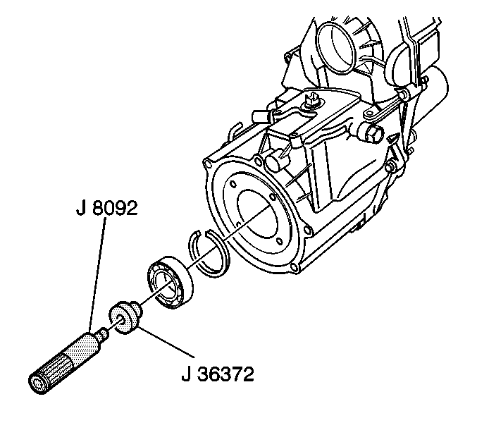
- Install the bearing retaining ring into the front
case.
- Using J 36372
and J 8092
, install the
front input shaft bearing.
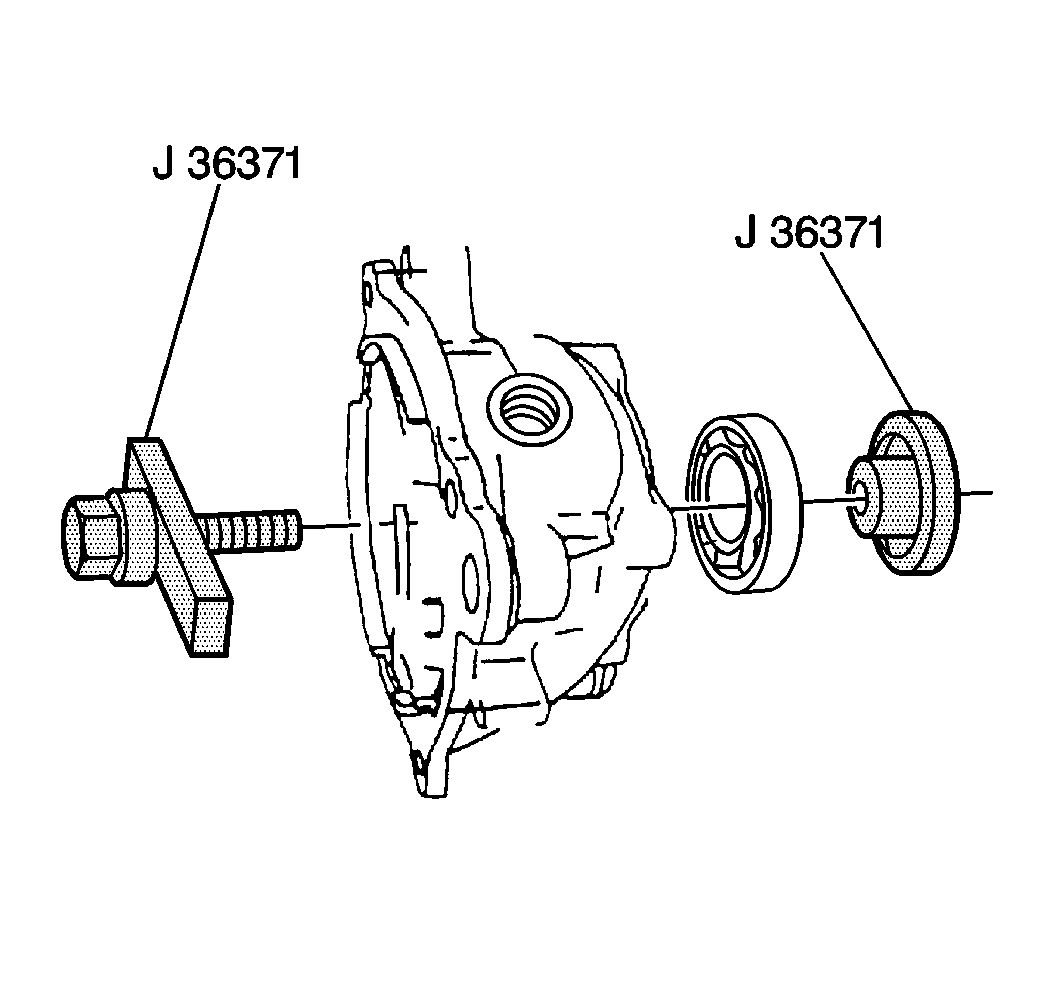
- Using J 36371
, install the output shaft rear bearing
into the output shaft rear retainer housing.
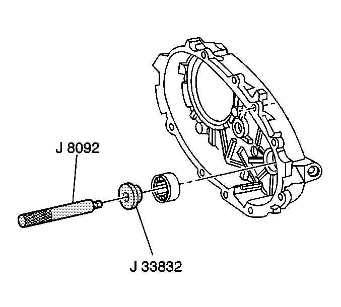
- Using J 33832
and J 8092
, install the front output shaft rear roller bearing.
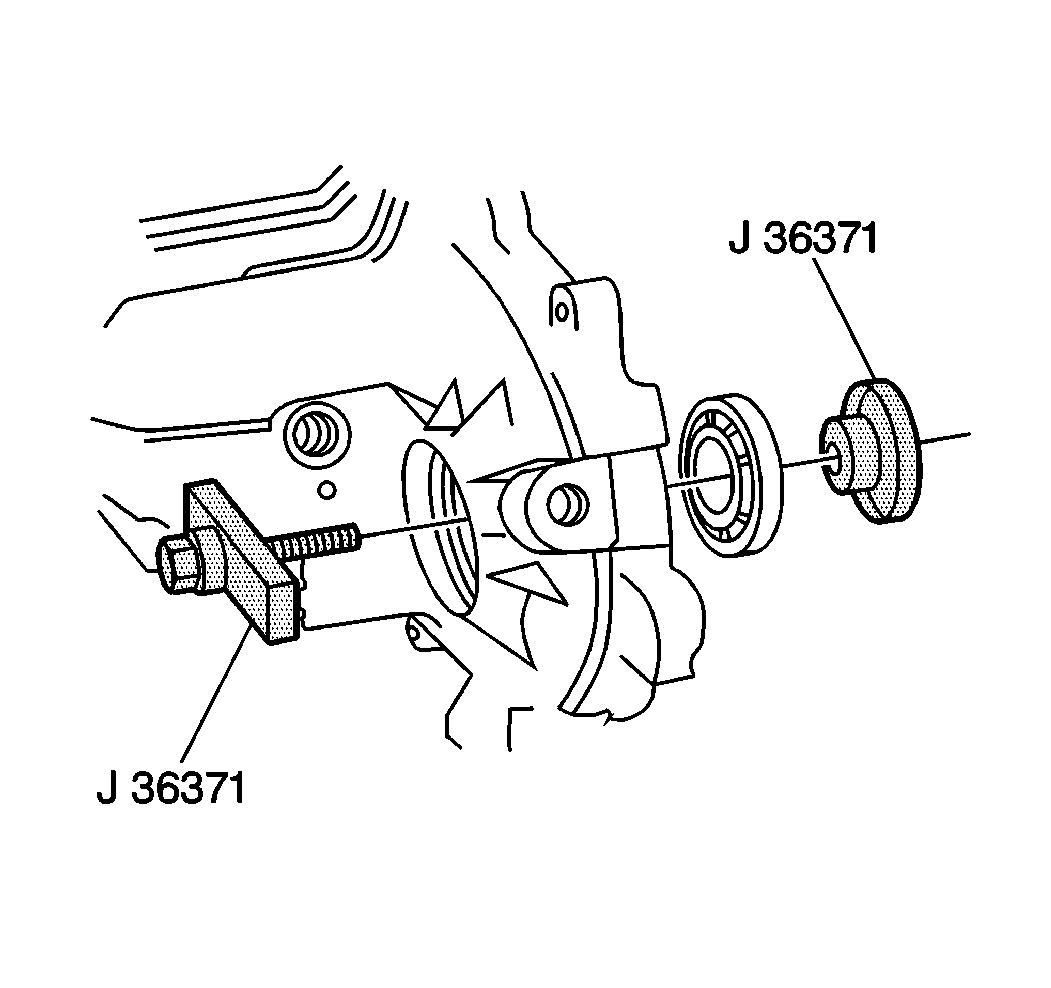
- Using J 36371
, install the front output shaft front
bearing.
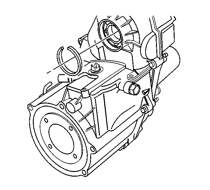
- Install the retaining ring into the front output
shaft case area.
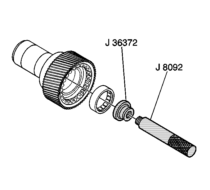
- Using J 36373
and J 8092
, install the input gear bearing into the input gear.
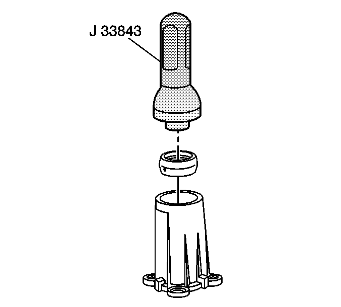
- Using J 33843
, install the output shaft extension
housing oil seal.
Lubricate the seal sealing lips with transfer case fluid.
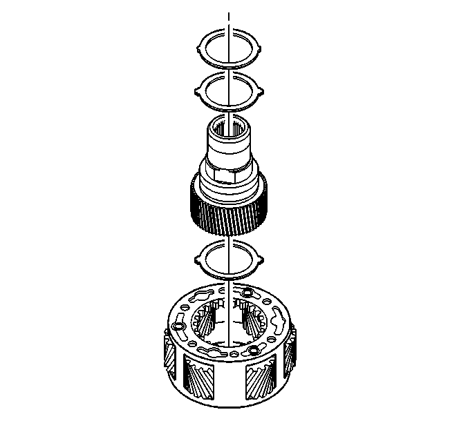
- Install the fiber washer into the planetary carrier.
- Install the input gear into the planetary carrier.
- Install the fiber washer onto the input gear.
- Install the steel spacer onto the input gear.
- Install the snap ring into the planetary carrier snap ring groove.
- Set the planetary carrier and input gear assembly aside.
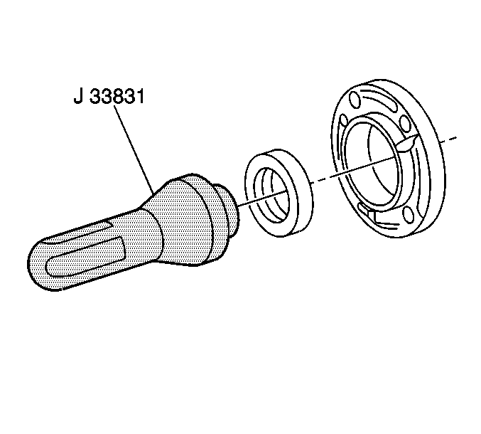
- Using J 33831
, install the input seal into the input bearing retainer.
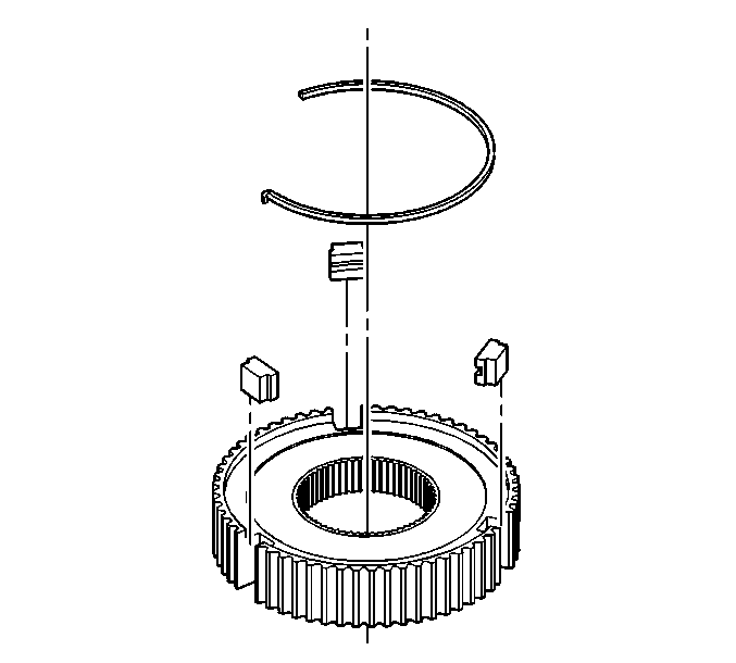
- Secure three struts to the synchronizer hub with the retaining ring.
| 16.1. | The hook end of the retaining ring is inserted into the first
strut to hold the strut into place. |
| 16.2. | Then second and third struts are held in place from in front by
the retaining ring. |
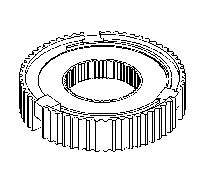
- Turn the synchronizer over and install the second retaining ring the
same as the first retaining ring was installed.
| • | Ensure the hook end of the second retaining ring is not installed
into the same strut as the first retaining ring hooked end. |
| • | Any one of the two remaining struts on the bottom side of the
synchronizer hub can be used as the starting point for installation of the
hooked end of the retaining ring. |
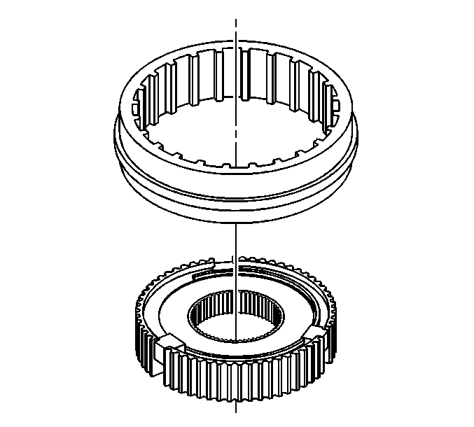
- Install the clutch sleeve over the synchronizer
hub.
| • | Ensure the spline of the clutch sleeve is aligned with the strut. |
| • | Ensure the struts are positioned into the strut pockets (recessed
area) of the clutch sleeve. |
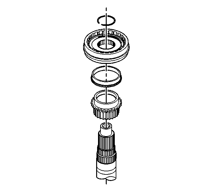
- Install the drive sprocket, synchronizer and sleeve assembly, synchronizer
stop ring, and retaining ring.
| • | Ensure the drive sprocket is installed with the cone end (clutch
teeth) toward the input end of the main shaft. |
| • | Ensure the synchronizer stop ring is positioned onto the cone
of the drive sprocket. |
| • | Ensure the clutch teeth mate with the drive sprocket teeth to
allow for the retaining ring installation. |
| • | With all the main shaft parts aligned correctly, the retaining
ring should slip and lock into the groove on the main shaft. |
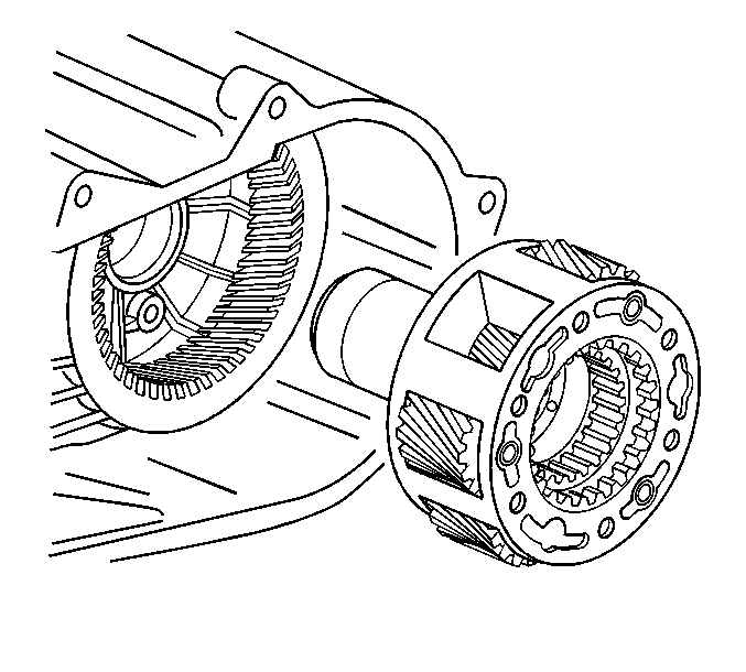
- Install the planetary assembly into the front
case.
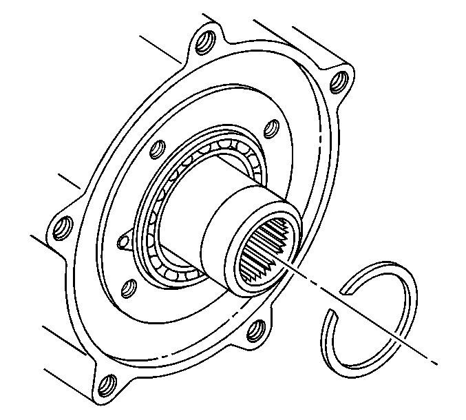
- Install the snap ring onto the input shaft.
Notice: Use the correct fastener in the correct location. Replacement fasteners
must be the correct part number for that application. Fasteners requiring
replacement or fasteners requiring the use of thread locking compound or sealant
are identified in the service procedure. Do not use paints, lubricants, or
corrosion inhibitors on fasteners or fastener joint surfaces unless specified.
These coatings affect fastener torque and joint clamping force and may damage
the fastener. Use the correct tightening sequence and specifications when
installing fasteners in order to avoid damage to parts and systems.
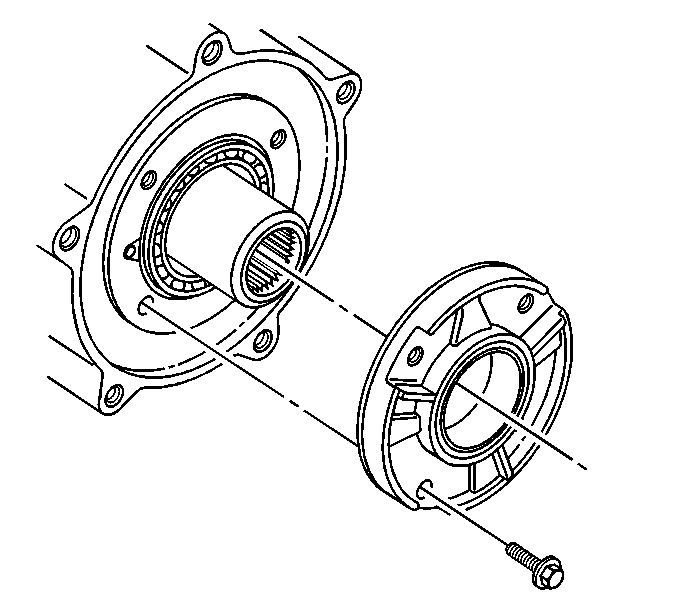
- Install the input
shaft bearing retainer to the front case.
| 22.1. | Apply a thin coat of RTV to the input shaft bearing retainer mating
surface. |
| 22.2. | Apply a threadlocker to the bearing retainer bolt threads. |
| 22.3. | Secure the bearing retainer to the front case with four bolts. |
Tighten
Tighten the bearing retainer bolts to 19 N·m (14 lb ft).
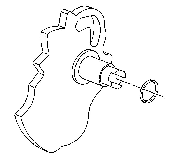
- Install the o-ring onto the sector shaft.
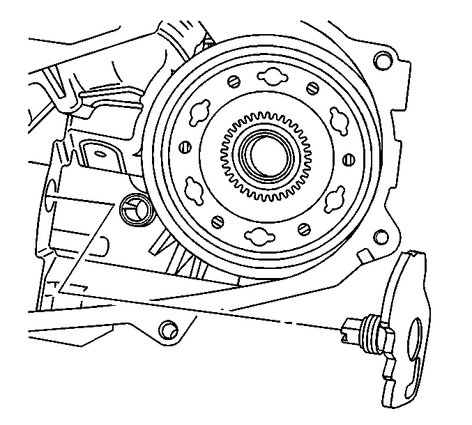
- Install the sector shaft into the front case.
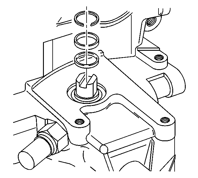
- Install the plastic sleeve and retaining ring
onto the sector shaft.
| 25.1. | Ensure the retaining ring is positioned into the second groove
toward the plastic sleeve on the sector shaft. |
| 25.2. | After installation of the retaining ring, ensure the retaining
ring is secured against the plastic sleeve. |
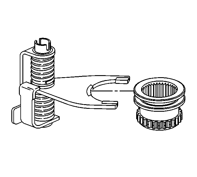
Important: Prior to installation of the low range fork, ensure the pads on the
low range fork have been replaced with new pads.
- Position the range shift hub into the low range fork.
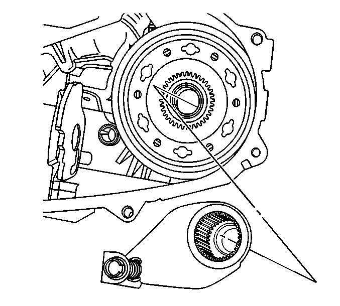
Important: During installation of the low range fork, sleeve, and hub assembly
onto the planetary assembly, ensure the roller of the sleeve assembly is positioned
onto the sector slot.
- Position the low range fork, sleeve, and hub assembly onto the planetary
assembly and case.
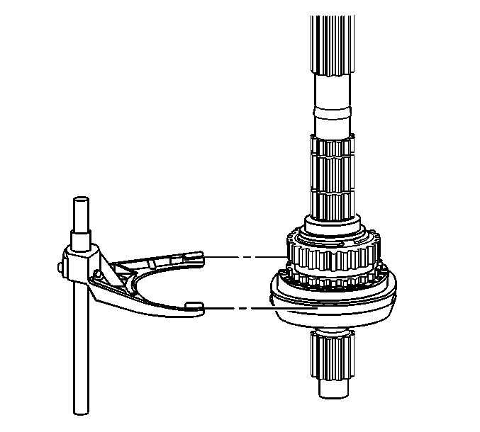
Important: Prior to installation of the mode fork, ensure the pads on the mode
fork have been replaced with new pads.
- Position the mode fork onto the mainshaft.
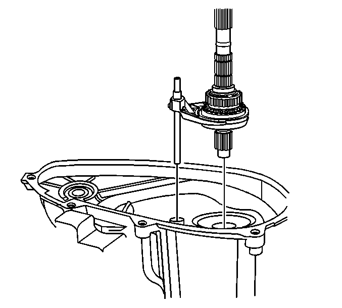
- Position the main shaft and mode fork into the
front case and sleeve assembly.
| 29.1. | Position the main shaft into the hub and planetary assembly. |
| 29.2. | Position the shaft of the mode fork into the sleeve assembly. |
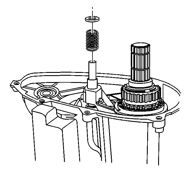
- Position the mode fork retaining spring and the
retaining spring cover onto the mode fork shaft.
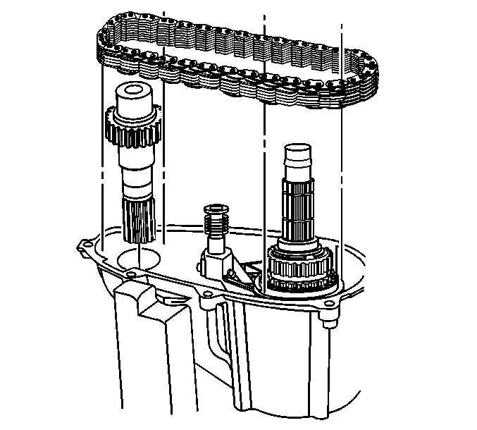
- Install the front output shaft and drive chain into the front case and
onto the main shaft.
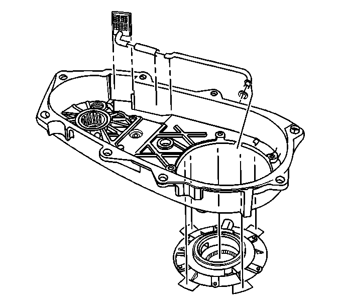
- Secure the rubber tube to the oil pickup screen
and oil pump tube
- Secure the oil pickup screen to the rear case.
- Position the o-ring into the oil pump port.
- Position the oil pump to the bottom of the rear case and secure
the oil pickup tube to the oil pump.
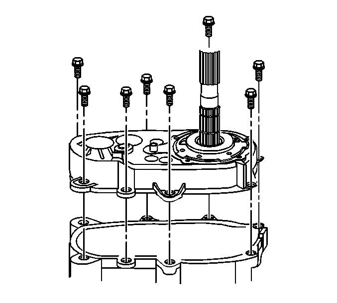
- Apply a thin coat of RTV sealant to the mating
surface of the front case.
- Position the rear case onto the front case.
- Apply a threadlocker to the case bolts.
- Install the two bolts with the washers into the doweled case holes.
- Install the remaining case bolts.
- Secure the rear case to the front case with the case bolts.
Tighten
Tighten the case bolts to 31N·m (23 lb ft).
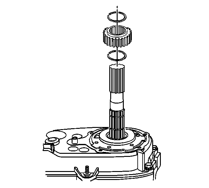
- Install the speedometer tone wheel retaining
ring onto the rear output shaft.
- Install the speedometer tone wheel onto the rear output shaft.
Ensure the tone wheel is flush against the retaining ring.
- Install the speedometer tone wheel second retaining ring.
Ensure the retaining ring is positioned into the groove in the rear
output shaft.
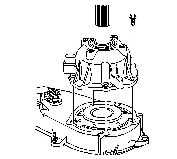
- Apply a thin coat of RTV sealant to the mating
surface of the rear output shaft bearing cover
Ensure no RTV is applied or push into the oil return port on the rear
output bearing cover
- Secure the rear output bearing cover to the case with the five
bolts.
Tighten
Tighten the bolts to 41N·m (30 lb ft).
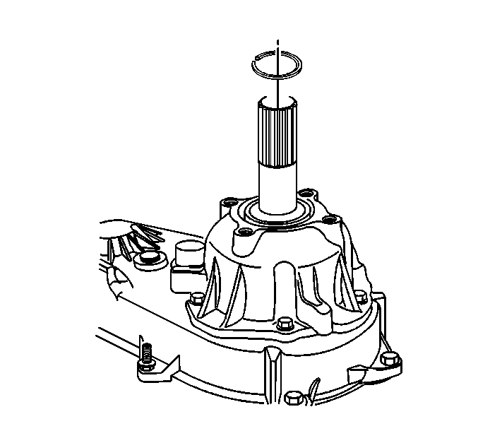
- Position the bearing retaining ring onto the
groove on the rear output shaft.
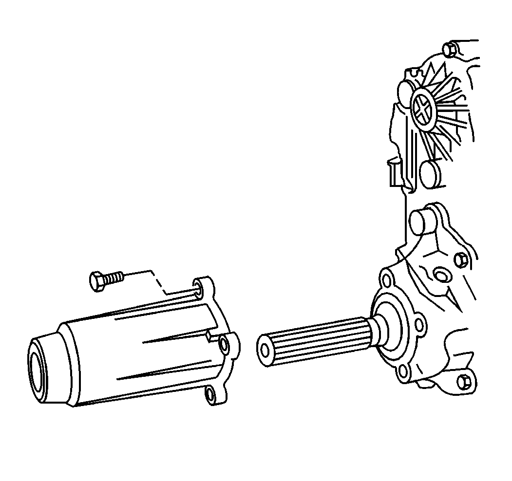
- Position the rear extension
housing onto the output bearing cover with the weep hole positioned down.
- Secure the rear extension housing to the output bearing cover
with four bolts.
Tighten
Tighten the bolts to 31N·m (23 lb ft).
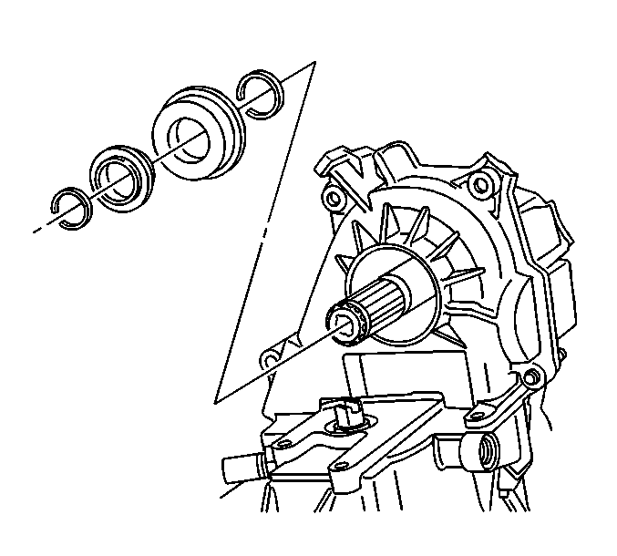
- Using J 33843
, Install the front output shaft seal into the front case and
onto the front output shaft.
- Install the retaining ring onto the output shaft groove.
- Install the plastic washer onto the output shaft and up against
the retaining ring.
- Install the second retainer ring into the groove at the end of
the output shaft.
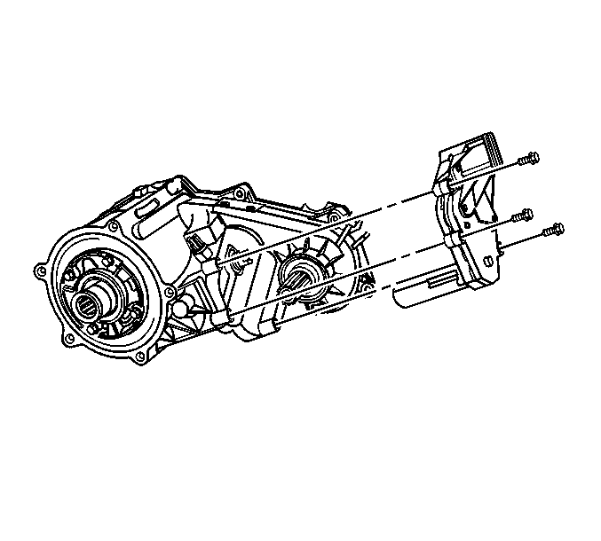
- Secure the motor/encoder to the transfer case
with three bolts.
Tighten
Tighten the bolts to 18N·m (13 lb ft).
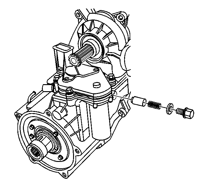
- Install the detent plunger, plunger
spring, o-ring, and plunger plug.
Tighten
Tighten the plunger plug to 15N·m (11 lb ft).
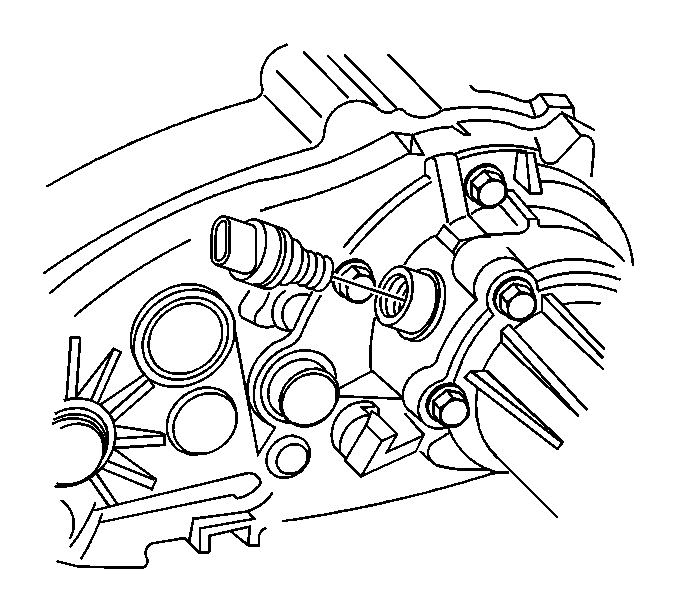
- Install the speed sensor.
Tighten
Tighten the speed sensor to 31N·m (23 lb ft).


