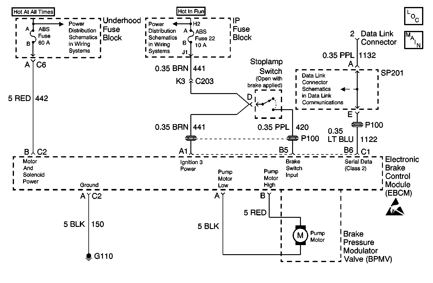
Circuit Description
The Instrument Panel Cluster (IPC) turns the ABS Indicator lamp on at bulb check for approximately 2 seconds when the ignition switch is turned to the ON position. Afterwards, the EBCM sends a class 2 message to the IPC which commands the ABS indicator lamp OFF. If the EBCM sets a Diagnostic Trouble Code (DTC), the EBCM sends a class 2 message to the IPC to command the ABS indicator lamp ON.
Diagnostic Aids
| • | It is very important that a thorough inspection of the wiring and connectors be performed. Failure to carefully and fully inspect wiring and connectors may result in misdiagnosis, causing part replacement with reappearance of the malfunction. |
| • | Thoroughly inspect any circuitry that may be causing the complaint for the following conditions: |
| - | Backed out terminals |
| - | Improper mating |
| - | Broken locks |
| - | Improperly formed or damaged terminals |
| - | Poor terminal-to-wiring connections |
| - | Physical damage to the wiring harness |
| • | The following conditions may cause an intermittent malfunction: |
| - | A poor connection |
| - | Rubbed-through wire insulation |
| - | A broken wire inside the insulation |
| • | If an intermittent malfunction exists refer to Testing for Intermittent Conditions and Poor Connections in Wiring Systems. |
Test Description
The numbers below refer to step numbers on the diagnostic table.
Step | Action | Value(s) | Yes | No |
|---|---|---|---|---|
DEFINITION: The ABS Indicator does not come ON during the IPC bulb check. | ||||
1 | Was the ABS Diagnostic System Check performed? | -- | Go to Step 2 | Go to Diagnostic System Check |
Does the red BRAKE indicator lamp turn ON at bulb check for approximately 2 seconds, then turn OFF? | -- | Go to Step 3 | Go to Step 5 | |
3 | Using a scan tool in the Instrument Panel Cluster (IPC) Special Functions menu, attempt to turn the ABS Lamp ON. Did the ABS Lamp turn ON? | -- | Go to Step 4 | Go to Step 5 |
4 | Using a scan tool from the 4WAL 3 Sensor (ABS) Special Functions menu, attempt to turn the ABS Lamp OFF then ON. Did the ABS Lamp turn OFF then ON? | -- | Go to Testing for Intermittent Conditions and Poor Connections in wiring systems | Go to Step 6 |
5 | Replace the Instrument Panel Cluster. Refer to Instrument Cluster Replacement . Is the replacement complete? | -- | Go to Diagnostic System Check | -- |
6 | Replace the EBCM. Refer to Electronic Brake Control Module Replacement . Is the replacement complete? | -- | Go to Diagnostic System Check | -- |
