Tools Required
| • | J 3289-20 Holding Fixture |
| • | J 8092 Universal Driver Handle |
| • | J 33831 Input Seal Installer |
| • | J 33843 Output Shaft Extension Housing Seal Installer |
| • | J 36370 Drive Sprocket Needle Bearing Installer |
| • | J 36371 Output Shaft Bearing Installer |
| • | J 36372 Input Sun Gear Needle Installer |
| • | J 38869 Rear Extension Seal Installer |
| • | J 45380 Transfer Case Rear Bushing Remover and Installer |
| • | J 45759 Assembly Fixture |
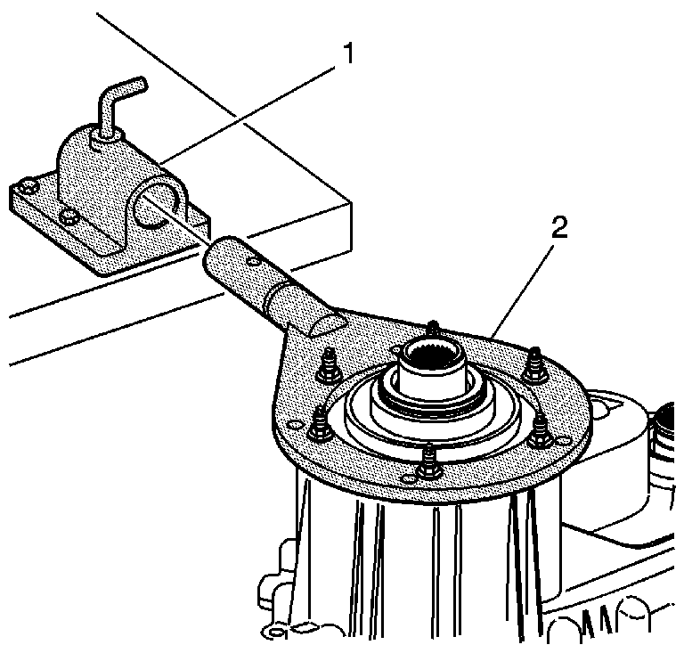
- Attach the J 45759 to the front transfer case using the adapter studs or bolts. The assembly procedures can be performed with the case mounted to the J 45759 .
- Install the J 45759 (2) into the J 3289-20 (1) and secure with the pivot pin.
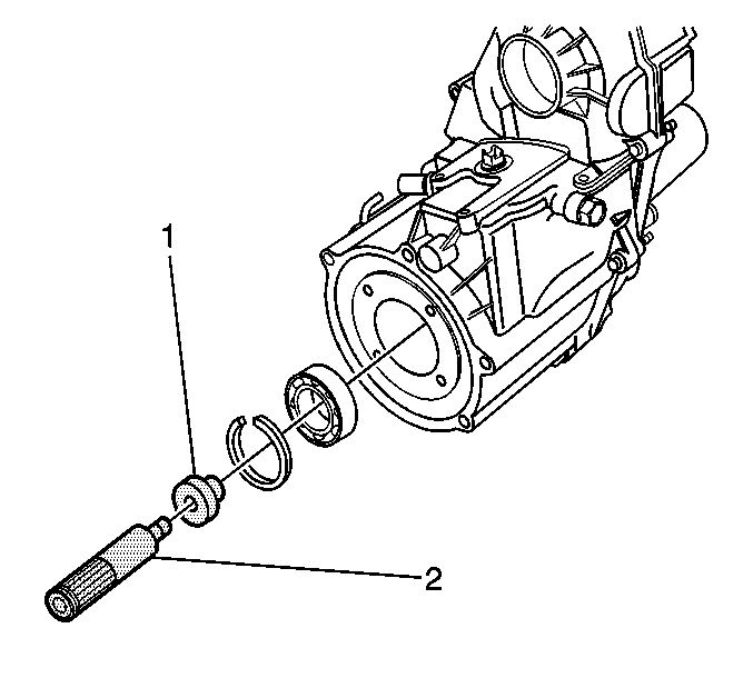
- Using the J 36372 (2) and the J 8092 (1), install the input bearing.
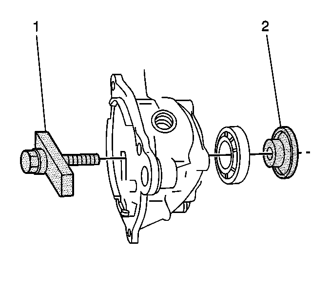
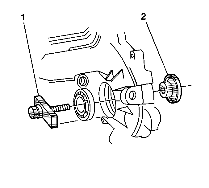
- Using the J 36371 (1 and 2), install the rear output shaft bearing.
- Using the J 36371 (1 and 2), install the front output shaft bearing.
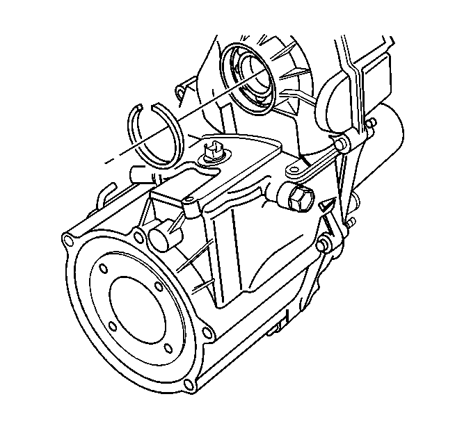
- Install the front output shaft bearing retaining ring.
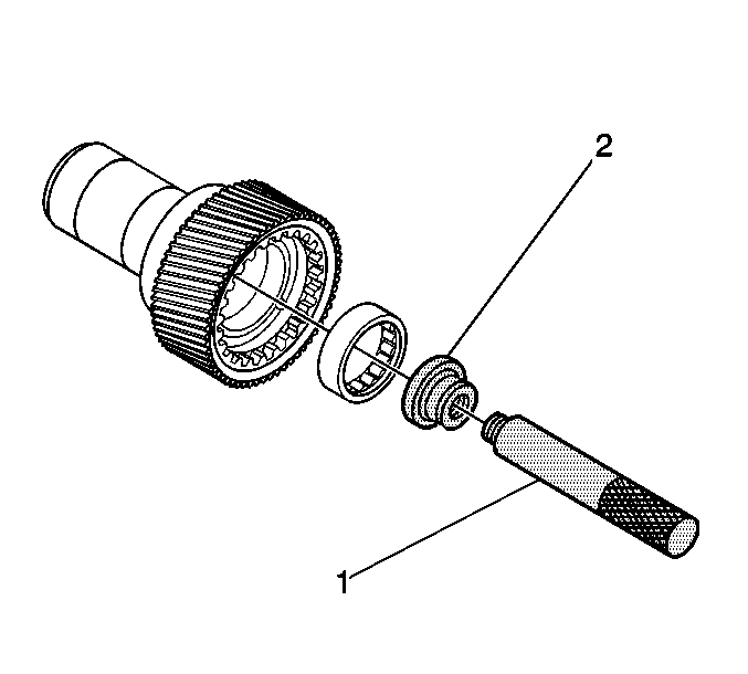
- Using the J 36370 (2) and the J 8092 (1), install the input shaft pilot bearing.
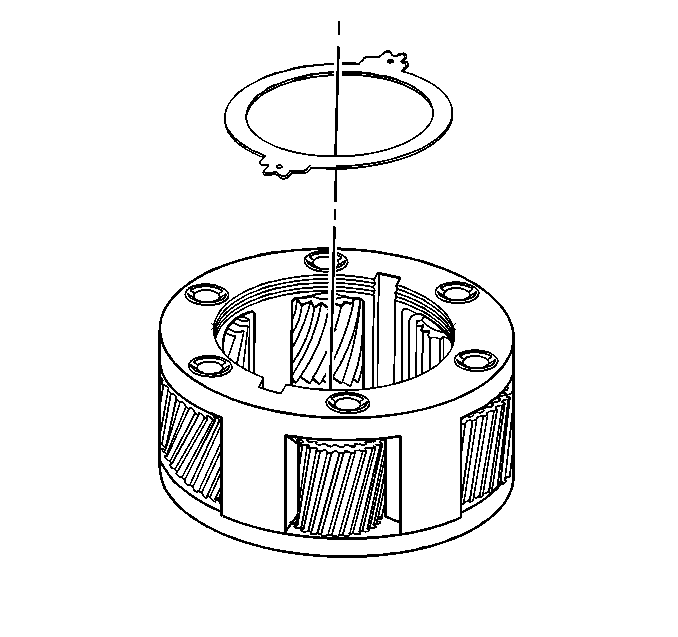
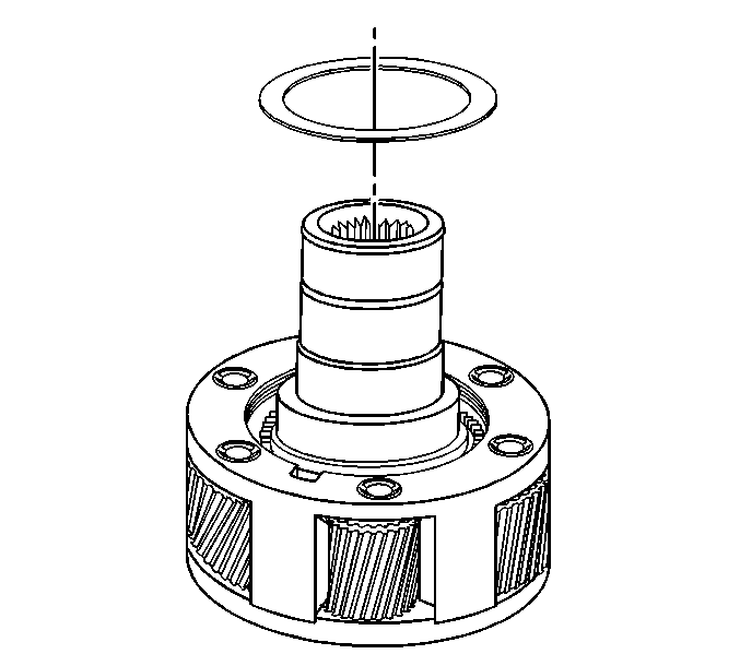
- Install the first input gear thrust washer.
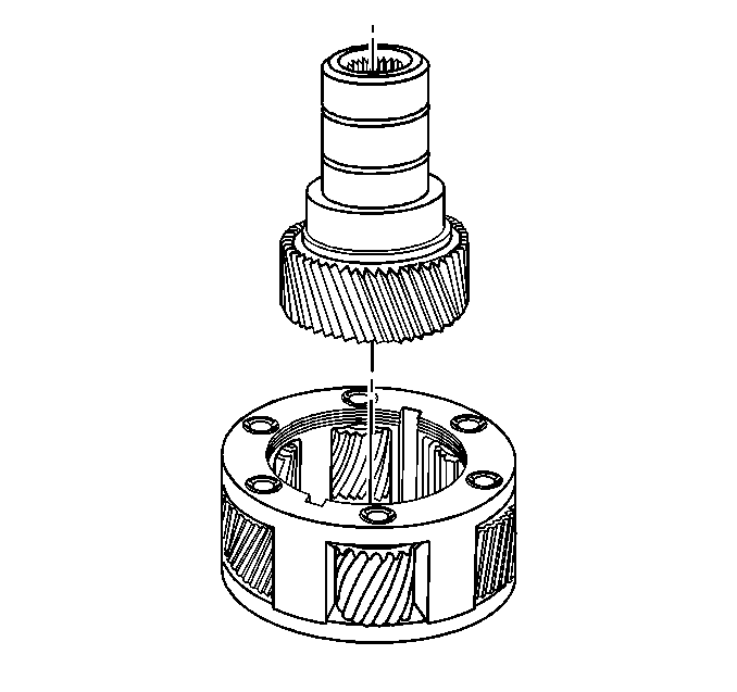
- Install the input gear.
- Install the second input gear thrust washer.
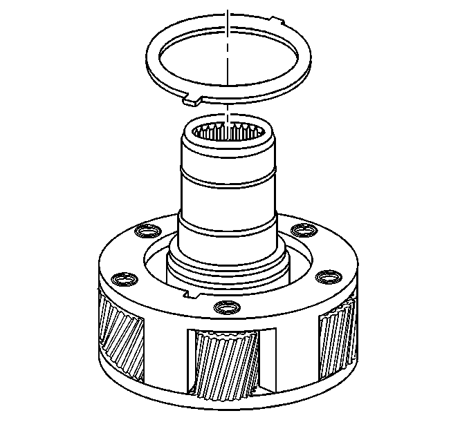
- Install the input gear thrust plate.
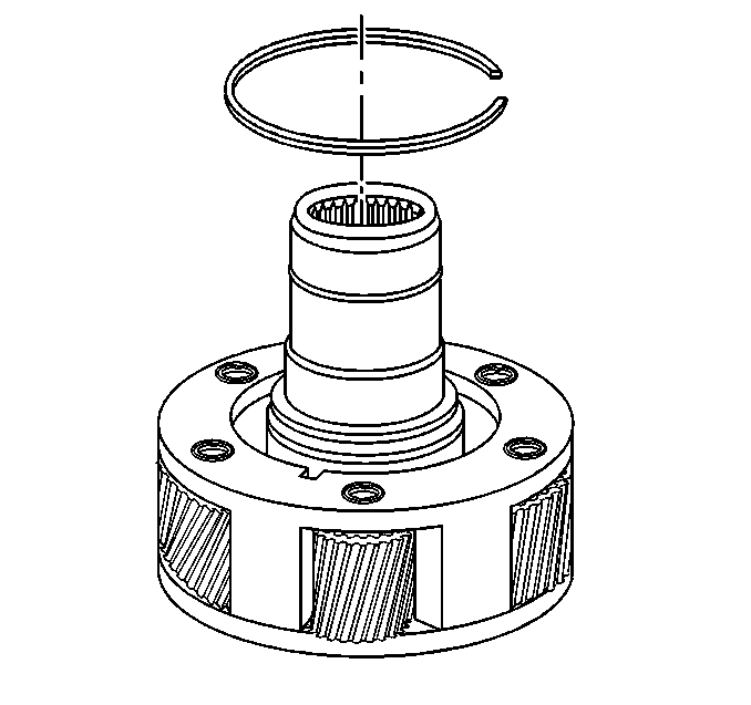
- Install the input gear retaining ring.
- Using the J 33831 , install the input shaft oil seal.
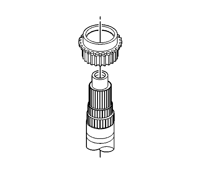
- Install the drive sprocket with the teeth facing away from the synchronizer assembly.
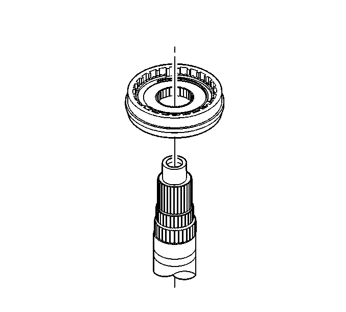
- Install the synchronizer stop ring with the teeth facing away from the synchronizer hub.
- Install the synchronizer hub assembly.
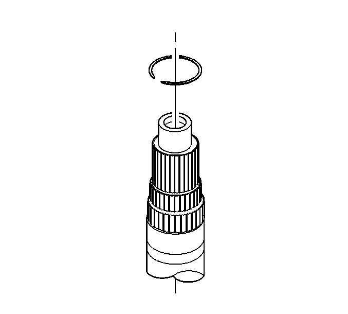
- Install the synchronizer hub retaining ring.
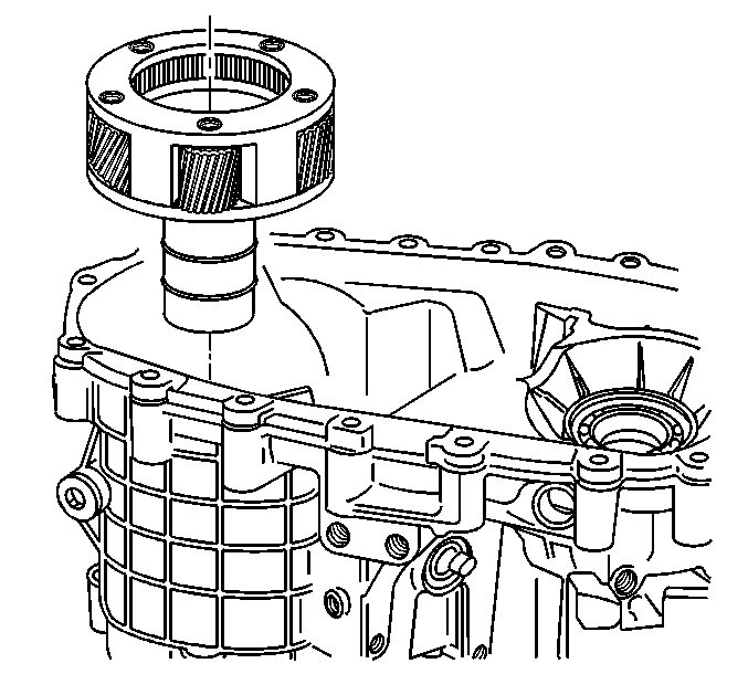
- Install the planetary assembly.
- Install the input shaft retaining ring.
- Apply a thin bead of silicone sealant GM P/N 12345739 (Canadian P/N 10953541) or equivalent.
- Apply threadlocker GM P/N 12345382 (Canadian P/N 10953489) or equivalent to the bolts.
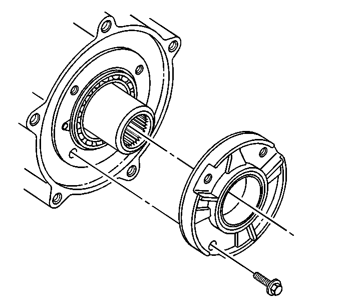
- Install the input bearing retainer and bolts.
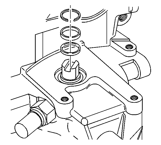
- Install the sector shaft assembly.
- Install the sector shaft O-ring.
- Install the plastic sleeve.
- Install the sector shaft retaining ring.
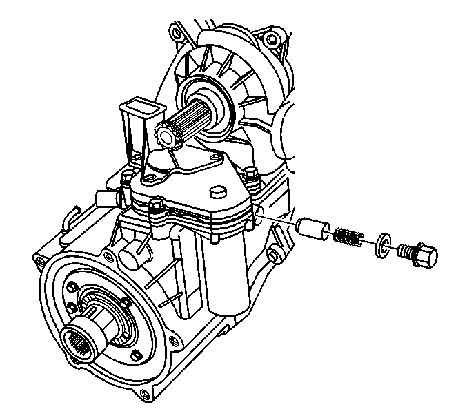
- Install the detent assembly.
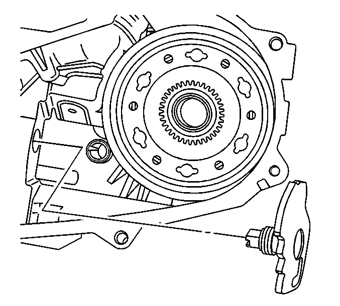
- Install the detent plug.
- Install the range shift sleeve.
- Install the range shift fork assembly.
- Install the mode fork on the rear output shaft.
- Install the rear output shaft assembly.
- Install the mode fork retaining spring and cover.
- Install the drive chain assembly.
- Install the O-ring in the oil pump assembly.
- Install the oil pump assembly.
- Install the oil pump pick-up assembly.
- Apply a thin bead 3 mm (1/8 inch) of silicone sealant GM P/N 12345739 (Canadian P/N 10953541) or equivalent.
- Install the rear case half to the front case half.
- Install the transfer case retaining bolts.
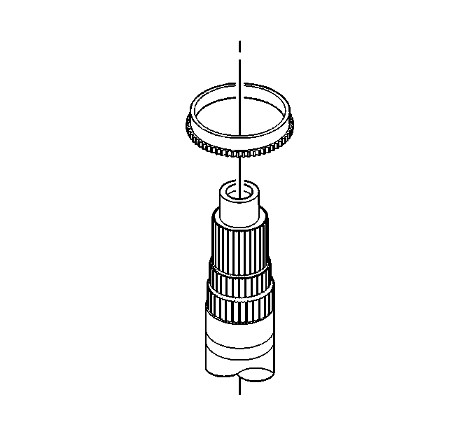
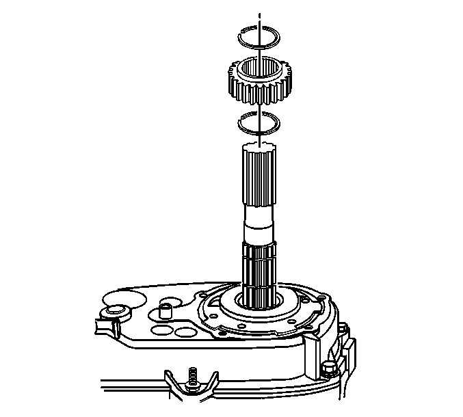
- Install the first tone wheel retaining ring.
- Install the tone wheel.
- Install the second tone wheel retaining ring.
- Apply a thin bead 3 mm (1/8 inch) of silicone sealant GM P/N 12345739 (Canadian P/N 10953541) or equivalent.
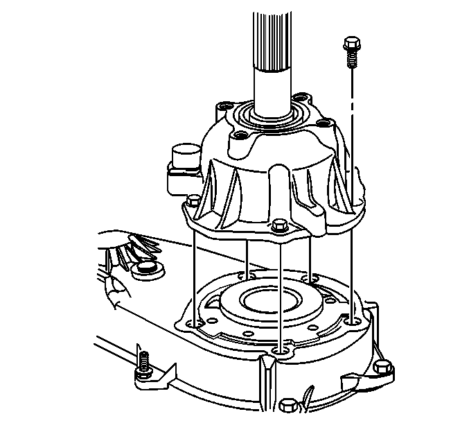
- Install the rear output shaft bearing retainer.
- Install the rear output shaft bearing retainer retaining bolts.
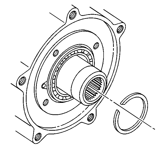
- Install the rear output shaft bearing retaining ring.
- Apply a thin bead 3 mm (1/8 inch) of silicone sealant GM P/N 12345739 (Canadian P/N 10953541) or equivalent.
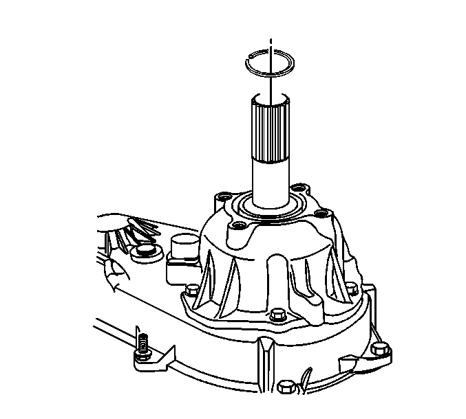
- Install the rear extension housing.
- Install the rear extension housing mounting bolts.
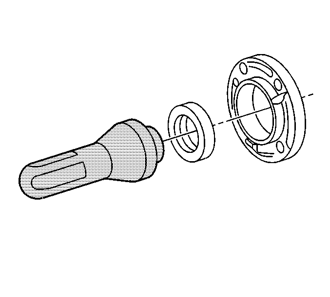
- Using the J 45380 , install a new rear output shaft bushing.
- Using the J 38869 , install the rear output shaft seal.
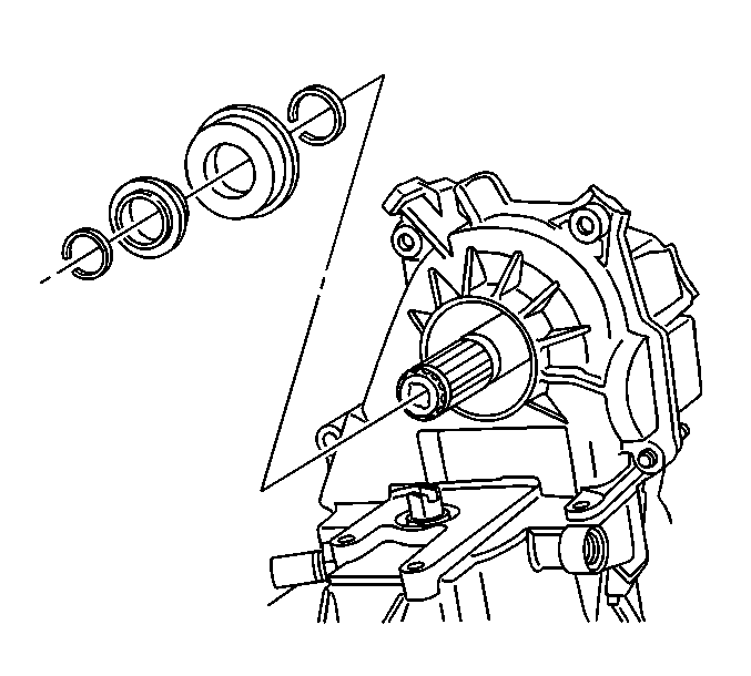
- Install the first front output shaft retaining ring.
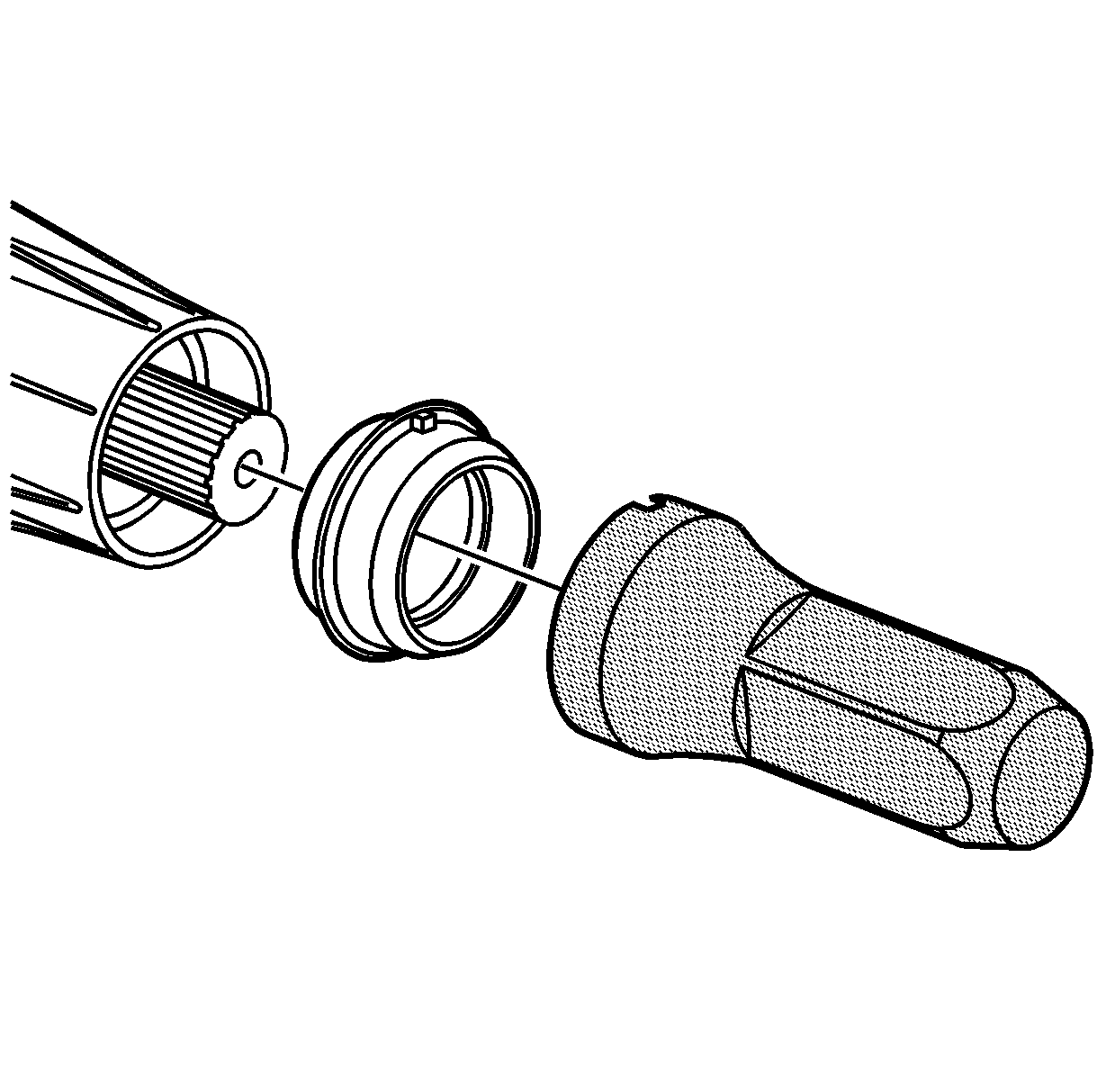
- Using the J 33843 , install the front output shaft seal.
- Install the front output shaft rubber washer.
- Install the second front output shaft retaining ring.
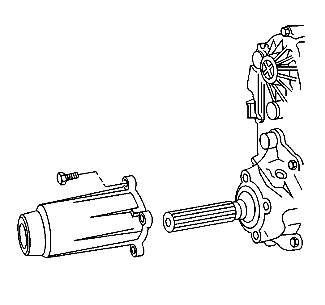
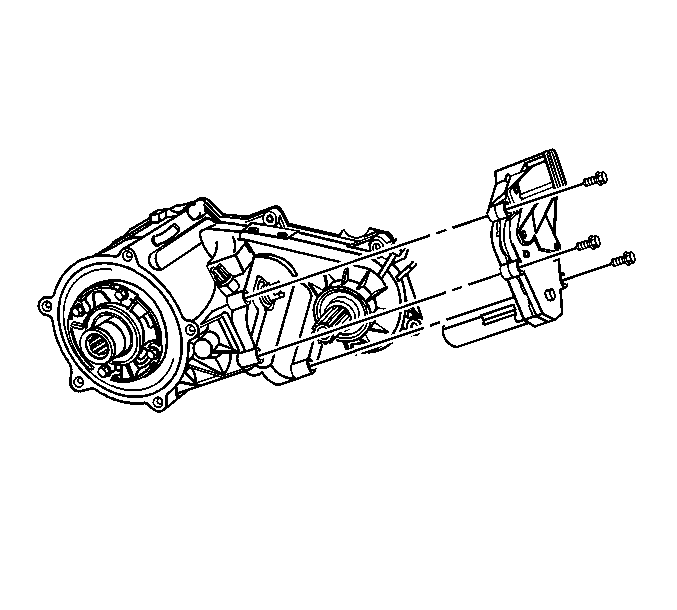
- Install the encoder motor assembly.
- Install the encoder motor mounting bolts.
- Install the transfer case speed sensor.
Important: It is not recommended to replace bearings separately. Some bearings may only be replaced in a subassembly.
Important: Ensure all sealing surfaces are clean of solvent and dirt.
Notice: Refer to Fastener Notice in the Preface section.
Tighten
Tighten the bearing retainer bolts to 19 N·m (14 lb ft).
Tighten
Tighten the detent plug to 20 N·m (15 lb ft).
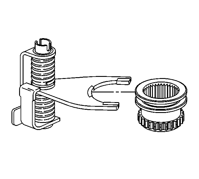
Important: Ensure the pads on the range shift fork have been replaced, before installing the range shift sleeve.
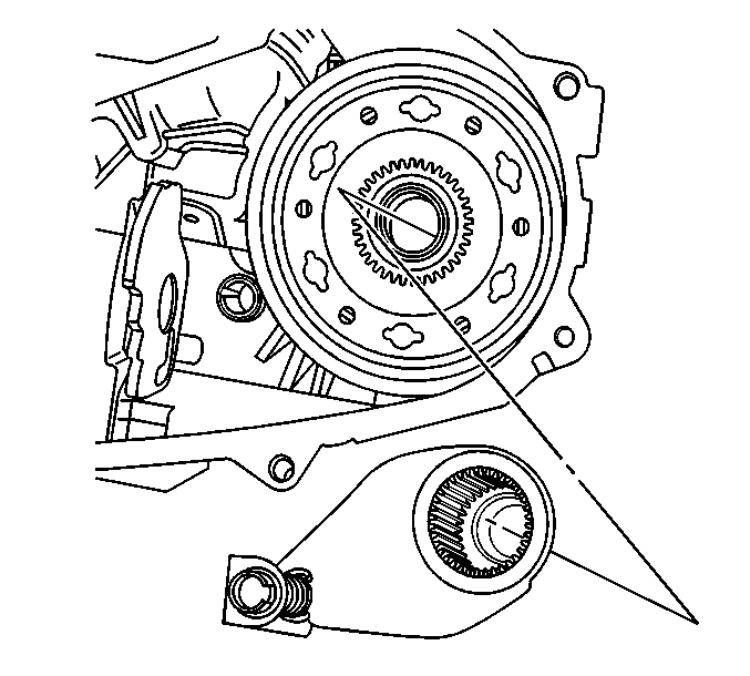
Important: Ensure the range shift fork assembly is properly seated on the sector assembly.
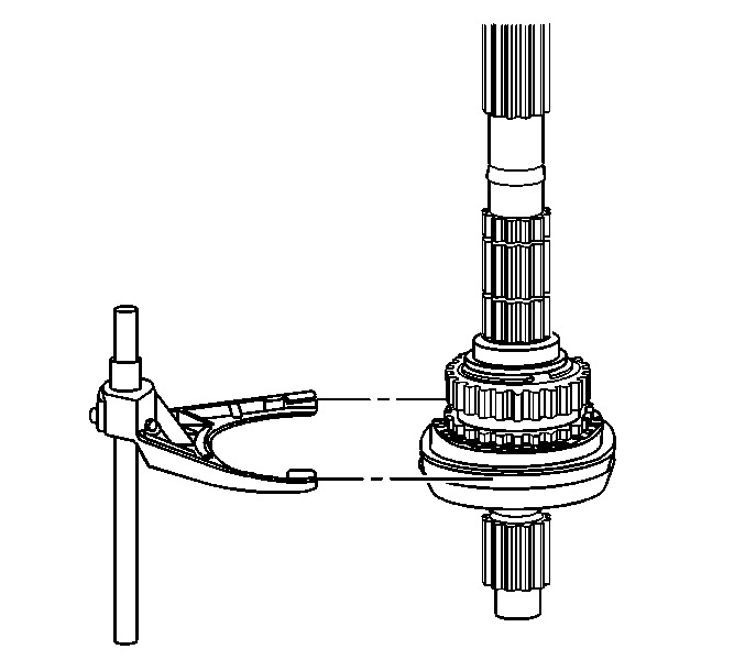
Important: Ensure the pads on the mode fork have been replaced, before installing the mode fork.
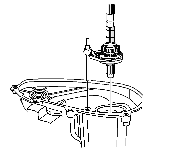
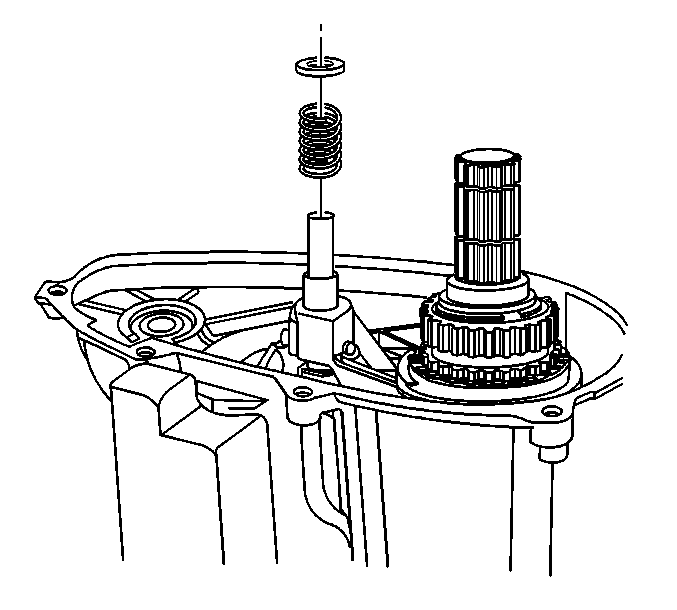
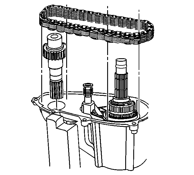
Important: Ensure the reference marks on the drive sprockets and the drive chain are aligned.
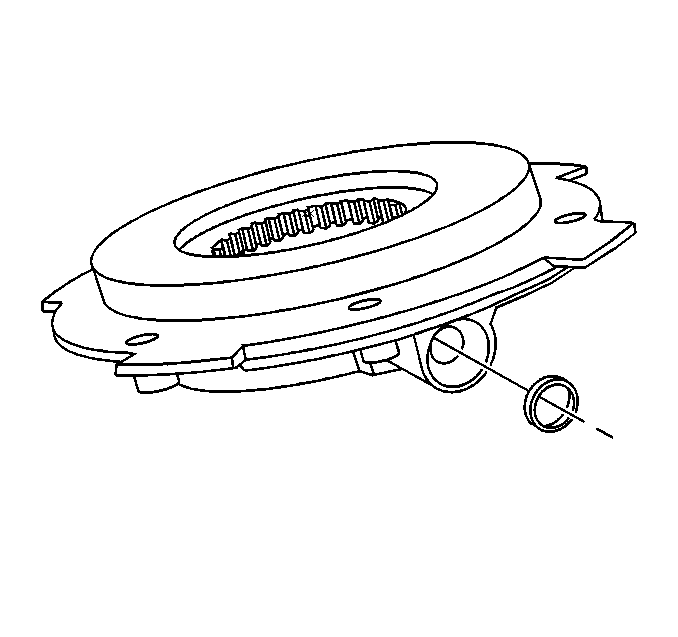
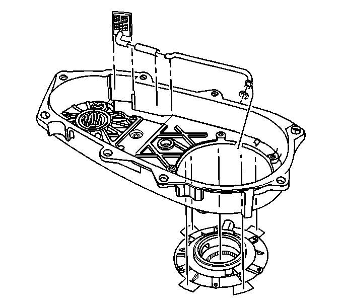
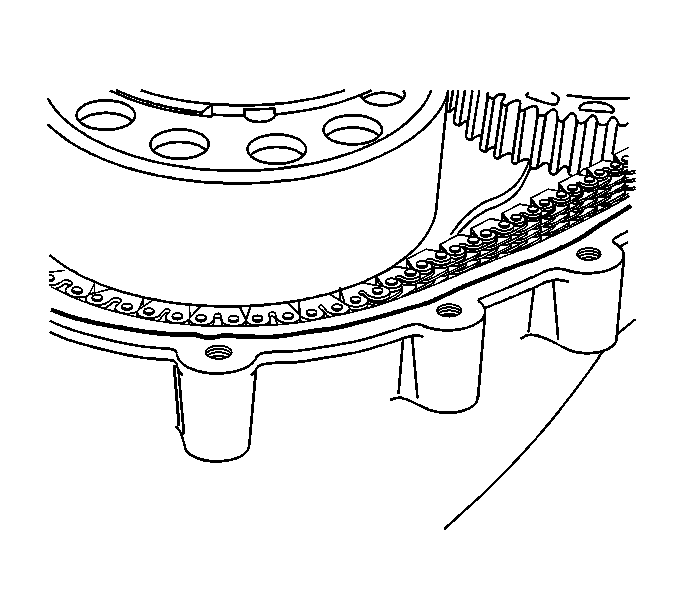
Notice: Apply the proper amount of sealant to the flange when assembling the transfer case. Excessive amounts of sealant can plug the oil pump screen, resulting in internal component failure.
Important: Ensure both sealing surfaces of the front case half and rear case half are free of dirt, oil, and cleaning solvent.
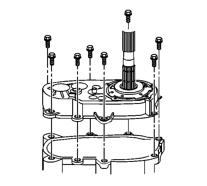
Important: Ensure the locating dowels are seated squarely in the front case.
Tighten
Tighten the transfer case retaining bolts to 31 N·m (23 lb ft).
Notice: Apply the proper amount of sealant to the flange when assembling the transfer case. Excessive amounts of sealant can plug the oil pump screen, resulting in internal component failure.
Important: Ensure both sealing surfaces of the retainer assembly and rear case half are free of dirt, oil, and cleaning solvent.
Tighten
Tighten the rear output shaft bearing retainer bolts to 27 N·m (20 lb ft).
Important: Ensure both sealing surfaces of the extension housing and rear case half are free of dirt, oil, and cleaning solvent.
Tighten
Tighten the rear extension housing mounting bolts to 31 N·m (23 lb ft).
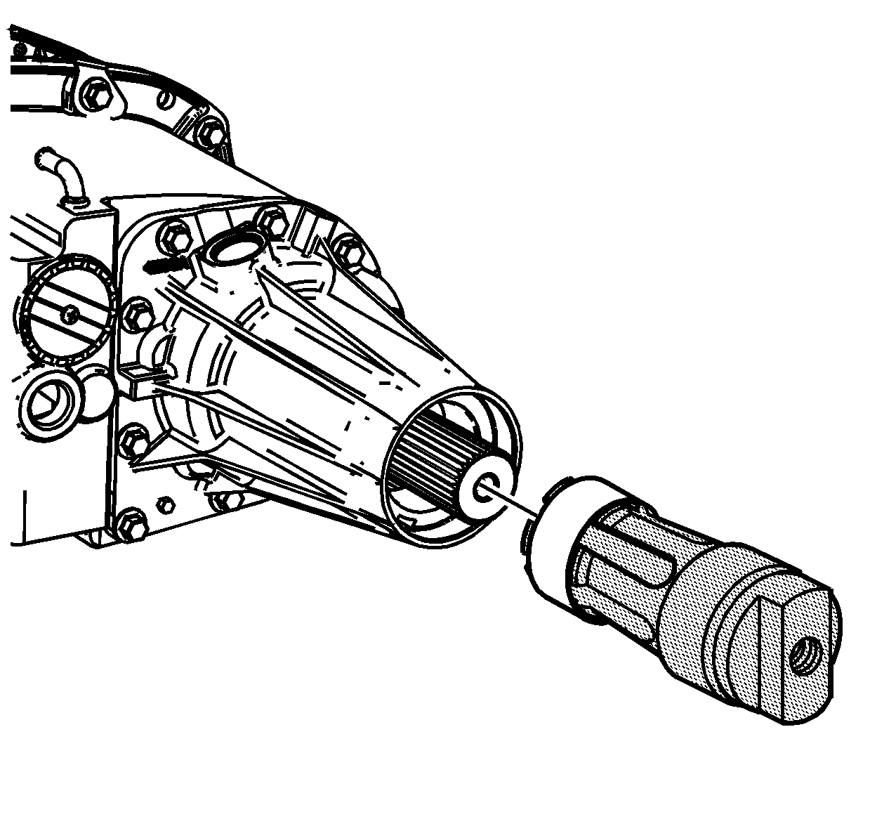
| 51.1. | Install the bushing on the finger section of the J 45380 . |
| 51.2. | Install the finger section to the main body of the J 45380 . |
| 51.3. | Position the bushing and tool to the case. |
| 51.4. | Using a hammer and the J 45380 , install the bushing. |
Tighten
Tighten the encoder motor mounting bolts to 20 N·m (15 lb ft).
Tighten
Tighten the transfer case speed sensor to 41 N·m (30 lb ft).
