Accelerator Controls Accelerator Cable
Removal Procedure
- Left sound insulator. Refer to Section 8C.
- Release cable retainer from lever assembly.
- Depress cable tangs and push forward toward engine compartment.
- Remove the accelerator cam splash shield.
- Remove the engine accelerator control cable out of bracket.
- Depress tangs on cable through cable throttle body bracket.
- Remove the cable from vehicle.

Installation Procedure
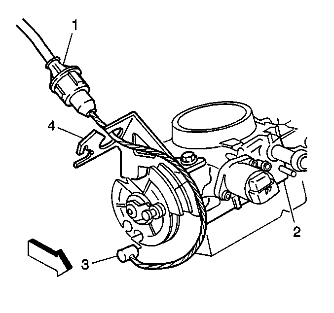
- Route cable (1) through cable bracket (4)
- Press cable upward through bracket.
- Install the engine accelerator control cable to cam.
- Install the accelerator cam splash shield.
- Install the cable to cowl making sure tangs fully expand and seat.
- Slip accelerator cable through slot in rod of accelerator pedal and install retainer in rod, being sure it is seated.
- Ensure cable is completely seated in throttle cam past retaining clips.
- Check for correct opening and closing positions by operating accelerator pedal. Make sure that the throttle valve reaches wide-open throttle position. If it does not, inspect for damaged or bent brackets, lever
- Install the left sound insulator. Refer to Section 8C.

Ensure tangs expand and properly seat.
Important: Flexible components (hoses, wires, conduits, etc.) must not be routed within 50 mm (2.0 in) of moving parts of accelerator linkage outboard of support unless routing is positively controlled.
Accelerator Controls Accelerator Cable Bracket
Removal Procedure
- Remove the cross slug (3) from throttle body slot.
- Depress tangs and remove cable (1).
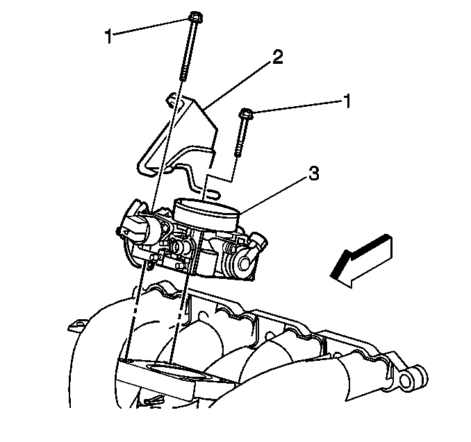
- Remove the bolts (1) to throttle body (3).
- Remove the bracket (2).


Installation Procedure
- Install the bracket (2) to throttle body (3).
- Install the bolts (1).
- Install the cable (1) to bracket, making certain tangs fully expand in bracket.
- Install the cross slug (3) into throttle body slot.
- Check for correct opening and closing positions by operating accelerator pedal. Make sure that the throttle valve reaches wide-open throttle position. If it does not, inspect for damaged or bent brackets, lever, or other components; or, for poor carpet fit under the accelerator pedal.

Tighten
Tighten the bolts to 6.5 N·m(58 lb in)
Notice: Use the correct fastener in the correct location. Replacement fasteners must be the correct part number for that application. Fasteners requiring replacement or fasteners requiring the use of thread locking compound or sealant are identified in the service procedure. Do not use paints, lubricants, or corrosion inhibitors on fasteners or fastener joint surfaces unless specified. These coatings affect fastener torque and joint clamping force and may damage the fastener. Use the correct tightening sequence and specifications when installing fasteners in order to avoid damage to parts and systems.

Important: Flexible components (hoses, wires, conduits, etc.) must not be routed within 50 mm (2.0 in) of moving parts of accelerator linkage outboard of support unless routing is positively controlled.
Accelerator Controls Accelerator Pedal
Removal Procedure
- Remove the left sound insulator. Refer to Section 8C.
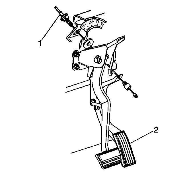
- Remove the release cable (1) retainer from the lever assembly.
- Remove the nuts to the cowl.
- Remove the pedal assembly (2).

Installation Procedure
- Install the pedal assembly (2) to the cowl.
- Install the nuts to the cowl.
- Slip the accelerator cable (1) through the slot in the rod and then install the retainer in the rod, being sure that it is seated.
- Install the left sound insulator. Refer to Section 8C.
- Inspect for correct opening and closing positions by operating the accelerator pedal. Make sure that the throttle valve reaches a wide-open throttle position. If it does not, inspect for damaged or bent brackets, levers, or other components; or, for poor carpet under the accelerator pedal.
Important: Flexible components (hoses, wires, conduits, etc.) must not be routed within 50 mm (2.0 in) of moving parts of accelerator linkage outboard of support unless routing is positively controlled.

Tighten
Tighten the nuts to 30 N·m (25 lb ft).
Notice: Use the correct fastener in the correct location. Replacement fasteners must be the correct part number for that application. Fasteners requiring replacement or fasteners requiring the use of thread locking compound or sealant are identified in the service procedure. Do not use paints, lubricants, or corrosion inhibitors on fasteners or fastener joint surfaces unless specified. These coatings affect fastener torque and joint clamping force and may damage the fastener. Use the correct tightening sequence and specifications when installing fasteners in order to avoid damage to parts and systems.
