Removal Procedure
Important: To prevent internal PCM damage, the ignition must be OFF when disconnecting or reconnecting power to PCM (for example, battery cable, PCM pigtail, PCM fuse, jumper cables, etc.). The ignition should be OFF for at least 10 seconds before disconnecting power to the PCM so the IAC valve has time to move to the engine OFF position.
- Disconnect the negative battery cable.
- Remove the RH hush panel.
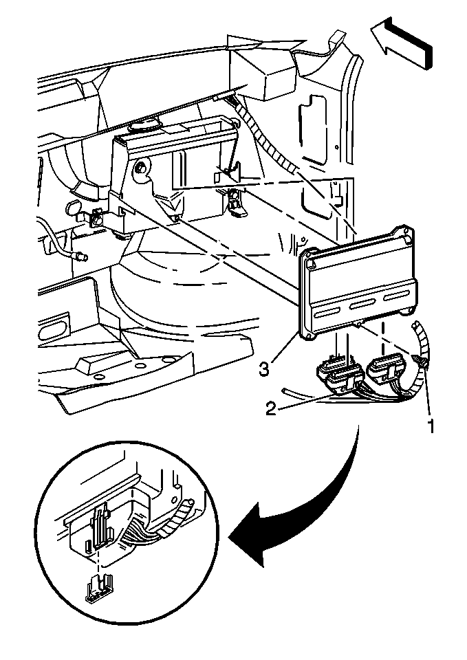
- Disconnect the PCM electrical connectors (2).
- Remove the PCM mounting bolt (1).
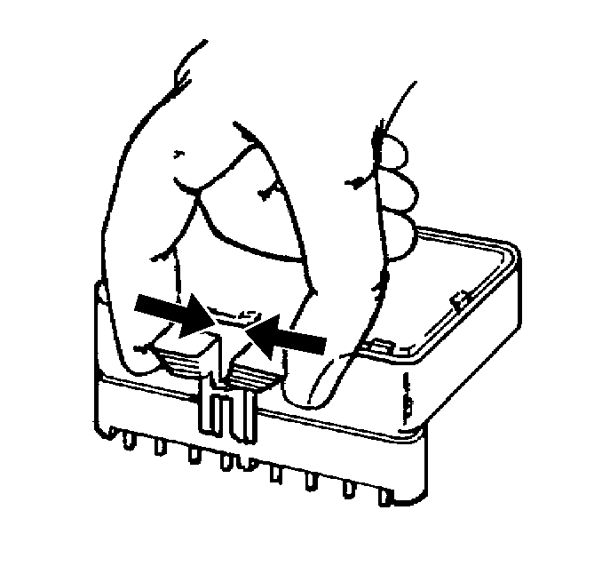
- Remove the retainer from the PCM.
- Slide the PCM (3) and retainer from the PCM bracket.
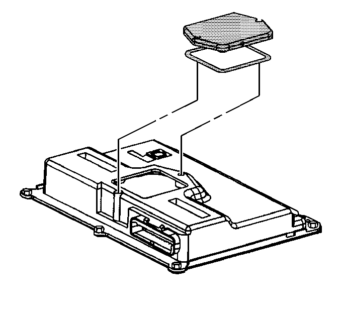
- Remove the KS module cover.
- Remove the KS module.

Important: PCM removal is eased when the glove box door is opened.
Notice: Clean the PCM housing of any debris that may cause damage to the PCM circuitry before removing the KS module cover.

Notice: In order to prevent possible electrostatic discharge (ESD) damage to the PCM or KS module, do not touch the connector pins or soldered components on the circuit board. Do not remove the integrated circuit boards from the carrier.

Installation Procedure
Important: Refer to the Latest Techline Information on Re-Programming or Flashing procedures.
- Install the KS module in the KS module socket.
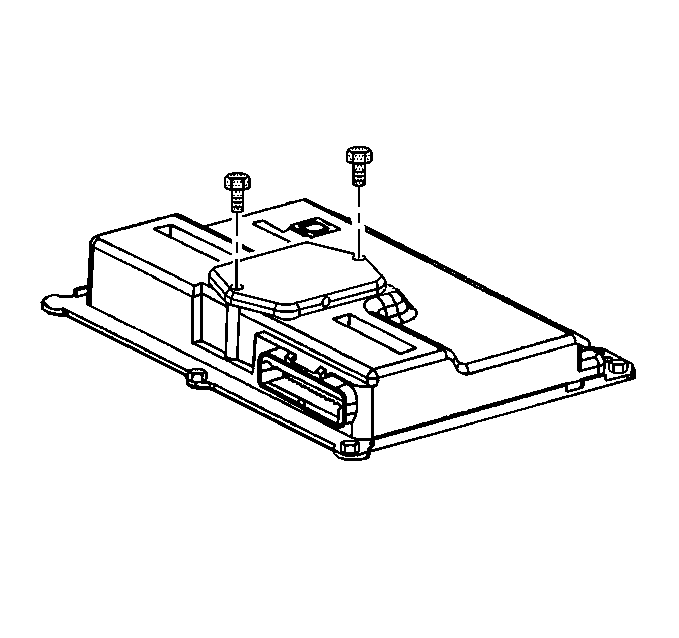
- Install the KS module cover.
- Slide the PCM (3) into the PCM retainer.
- Install the PCM mounting bolt (1).
- Connect the PCM electrical connectors (2).
- Install the RH hush panel.
- Connect the Negative battery cable.


Tighten
Tighten the KS module cover screws to 2.8-3.2 N·m
(25-28 lb. in.).
Notice: Use the correct fastener in the correct location. Replacement fasteners must be the correct part number for that application. Fasteners requiring replacement or fasteners requiring the use of thread locking compound or sealant are identified in the service procedure. Do not use paints, lubricants, or corrosion inhibitors on fasteners or fastener joint surfaces unless specified. These coatings affect fastener torque and joint clamping force and may damage the fastener. Use the correct tightening sequence and specifications when installing fasteners in order to avoid damage to parts and systems.

Tighten
PCM mounting bolt to 8-12 N·m (6-9 lb.
ft.).
