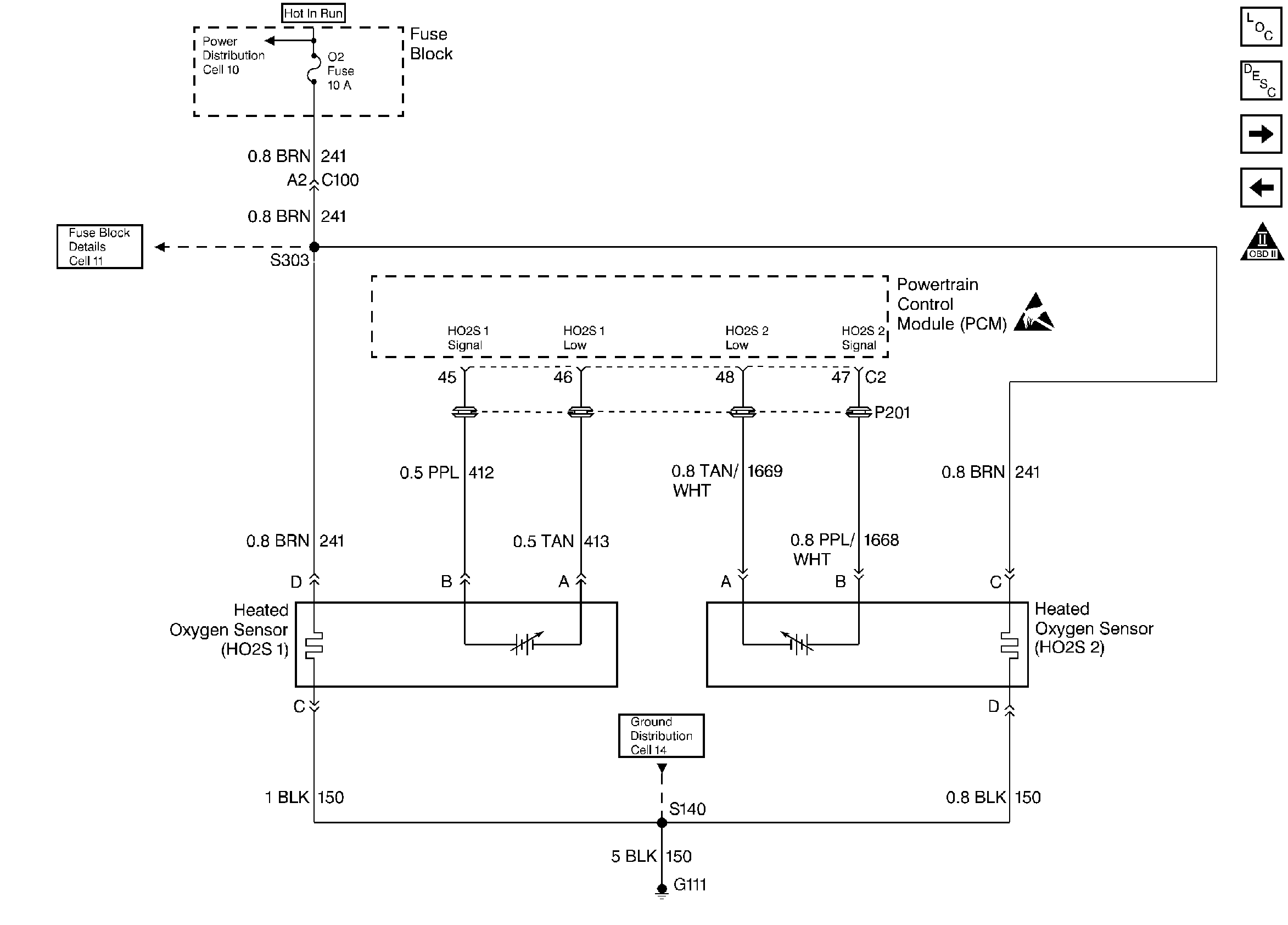
Refer to
Heated Oxygen Sensors

.
Circuit Description
To control emissions of Hydrocarbons (HC), Carbon Monoxide (CO), and Oxides of Nitrogen (NOx), a three-way catalytic converter is used. The catalyst within the converter promotes a chemical reaction which oxidizes the HC and CO present in the exhaust gas, converting them into harmless water vapor and carbon dioxide. The catalyst also reduces NOx, converting it to nitrogen. The PCM has the ability to monitor this process using the HO2S 1 and the HO2S 2 heated oxygen sensors. The HO2S 1 sensor produces an output signal which indicates the amount of oxygen present in the exhaust gas entering the three-way catalytic converter. The HO2S 2 sensor produces an output signal which indicates the oxygen storage capacity of the catalyst this in turn indicates the catalysts ability to convert exhaust gases efficiently. If the catalyst is operating efficiently, the HO2S 1 signal will be far more active than that produced by the HO2S 2 sensor. If the HO2S 2 signal voltage remains excessively high for an extended period of time, DTC P0138 will be set.
Conditions for Setting the DTC
| • | No active misfire, fuel injector circuit, TP sensor, EVAP, IAT sensor, MAP sensor, Fuel trim, EGR, ECT sensor, MAF sensor or CKP sensor DTC(s) present. |
| • | Engine coolant temperature above 75°C (167°F) |
| • | Throttle angle between 5% and 40%. |
| • | HO2S 2 signal voltage remains above 999mV during normal closed loop operation. |
OR
| • | HO2S 2 signal voltage remains above 800 mV during deceleration fuel mode operation. |
| • | Either condition for up to 50 seconds. |
Action Taken When the DTC Sets
| • | The PCM will illuminate the malfunction indicator lamp (MIL) during the second consecutive trip in which the diagnostic test has been run and failed. |
| • | The PCM will store conditions which were present when the DTC set as Freeze Frame and Failure Records data. |
Conditions for Clearing the MIL/DTC
| • | The PCM will turn OFF the MIL during the third consecutive trip in which the diagnostic has been run and passed. |
| • | The History DTC will clear after 40 consecutive warm-up cycles have occurred without a malfunction. |
| • | The DTC can be cleared by using the scan tool. |
Diagnostic Aids
Check for the following conditions:
| • | Fuel pressure. An excessively rich fuel mixture can cause a DTC P0138 to be set. Refer to Fuel System Diagnosis. |
| • | Rich injector(s). Perform Injector Balance Test. |
| • | Leaking injector. Refer to Fuel System Diagnosis. |
| • | Evaporative emissions (EVAP) canister purge. Check for fuel saturation. If full of fuel, check canister control and hoses. Refer to Evaporative Emission (EVAP) Control System. |
| • | MAF sensor. Disconnect the MAF sensor and see if rich condition is corrected. If so, replace MAF sensor. |
| • | Check for a leaking fuel pressure regulator diaphragm by checking vacuum line to regulator for the presence of fuel. |
| • | TP sensor. An intermittent TP sensor output will cause the system to go rich, due to a false indication of the engine accelerating. |
| • | Shorted Heated Oxygen Sensor (HO2S). If the HO2S is internally shorted the HO2S voltage displayed on the scan tool will be over 1 volt. Try disconnecting the affected HO2S and jumper the HO2S low circuit to ground with the key ON, engine OFF. If the displayed HO2S voltage changes from over 1000mV to around 450mV, replace the HO2S. Silicon contamination of the HO2S can also cause a high HO2S voltage to be indicated. This condition is indicated by a powdery white deposit on the portion of the HO2S exposed to the exhaust stream. If contamination is evident, replace the affected HO2S. |
| • | Open HO2S Signal or Low Circuit or Faulty HO2S. A poor connection or open in the HO2S signal or low circuit can cause the DTC to set during deceleration fuel mode. An HO2S which is faulty and not allowing a full voltage swing between the rich and lean thresholds can also cause this condition. Operate the vehicle while monitoring the HO2S voltage with a scan tool. If the HO2S voltage is limited within a range between 300mV to 600mV, check the HO2S signal and low circuit wiring and associated terminal connections . If the wiring and connections are OK, replace the HO2S. |
Test Description
Number(s) below refer to the step number(s) on the Diagnostic Chart.
Step | Action | Value(s) | Yes | No |
|---|---|---|---|---|
1 | Was the Powertrain On-Board Diagnostic System Check performed? | -- | Go to Powertrain OBD System Check | |
2 |
Does the HO2S 2 voltage remain above the specified value? | 999 mV | ||
3 |
Does scan tool indicate DTC P0138 failed this ignition? | -- | Refer to Diagnostic Aids | |
4 | Disconnect HO2S 2 and jumper HO2S low circuit to ground. Does scan tool indicate HO2S 2 voltage near the specified value? | 450 mV | Refer to Diagnostic Aids | |
5 |
Does DVM indicate a voltage above specified value? | 999 mV | ||
6 | Repair short to voltage in the HO2S 2 signal circuit. Refer to Heated Oxygen Sensor (O2S) Repair in Repair Procedures Electrical Diagnosis section 8A. Is action complete? | -- | -- | |
7 | Replace the PCM. Important: Replacement PCM must be programmed. Refer to PCM Replacement/Programming. Is action complete? | -- | -- | |
8 |
Does scan tool indicate DTC P0138 failed this ignition? | -- | Repair complete |
