Important: Use care when handling the crankshaft. Avoid damage to the bearing surfaces
or the lobes of the crankshaft position reluctor ring. Damage to the teeth
of the crankshaft position reluctor ring may effect OBD II system
performance.
- Clean the crankshaft of the following elements:
- Thoroughly clean all oil passages and inspect for restrictions
or burrs.
Caution: Wear safety glasses in order to avoid eye damage.
- Dry the crankshaft with compressed air.
Important: Reluctor ring teeth should not have imperfections on the rising or falling
edges.
Imperfections of the reluctor ring teeth may effect OBD II system performance.
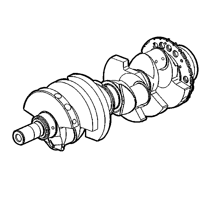
- Perform a visual inspection of the crankshaft for damage.
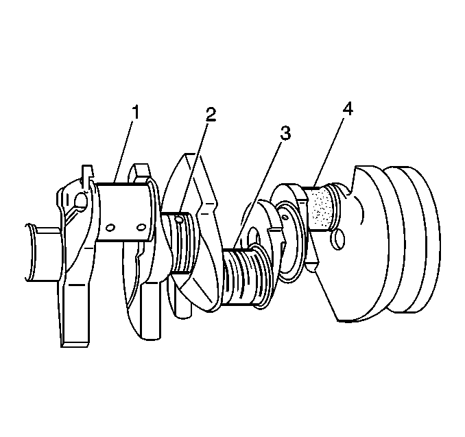
- Inspect the crankshaft
journals for wear (1).
Journals should be smooth with no signs of scoring, wear, or damage.
- Inspect the crankshaft journals for grooves or scoring (2).
- Inspect the crankshaft journals for scratches or wear (3).
- Inspect the crankshaft journals for pitting or imbedded bearing
material (4).
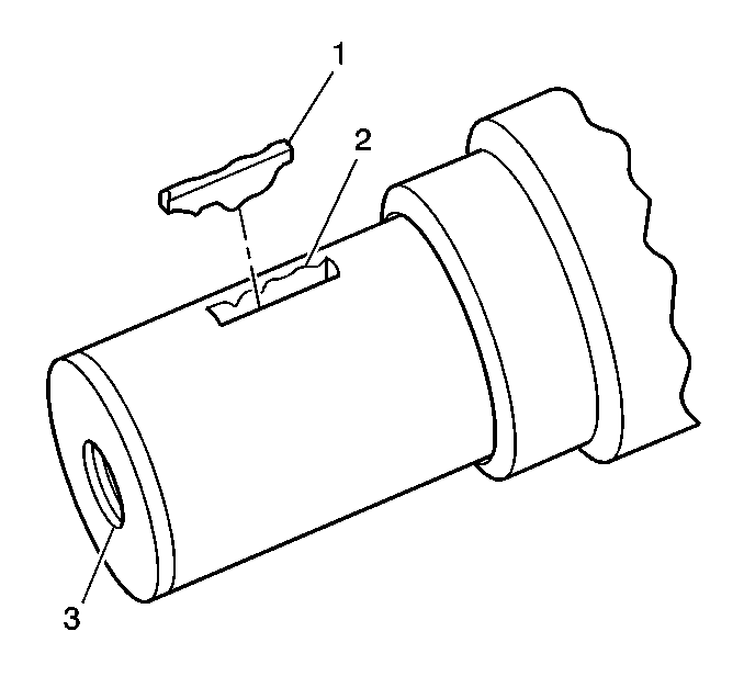
- Inspect the woodruff keys
(crankshaft balancer) (1), the keyway (2), and the threaded
hole (3) for damage.
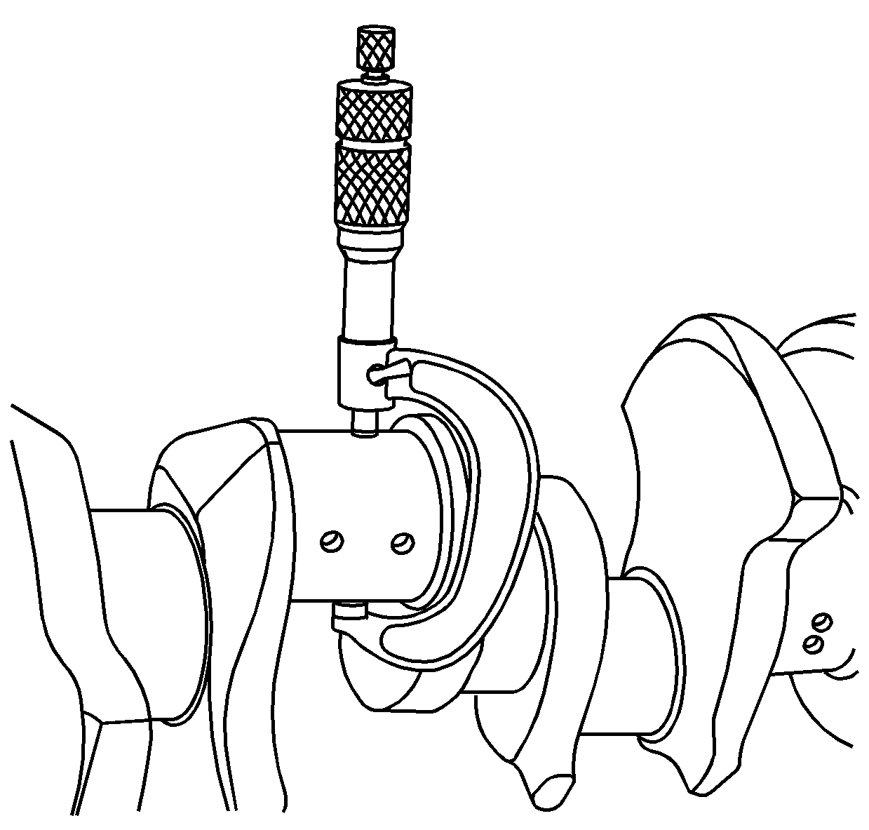
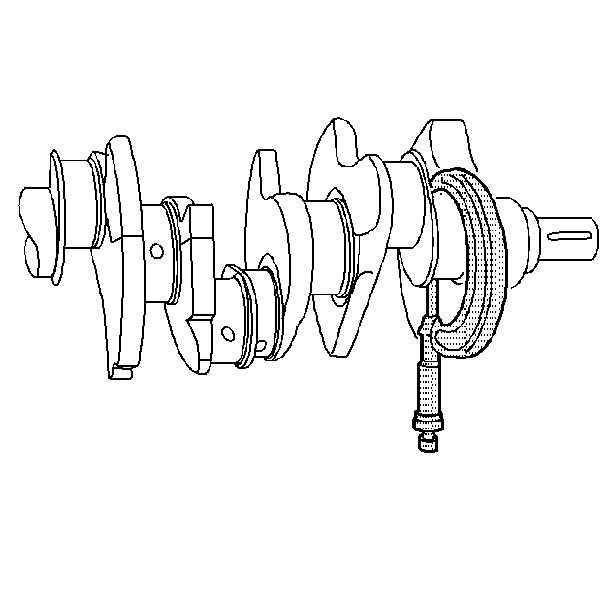
- Measure the crankshaft
journals for out-of-round. Refer to
Engine Mechanical Specifications
.
- Measure the crankshaft journals for taper. Refer to
Engine Mechanical Specifications
.
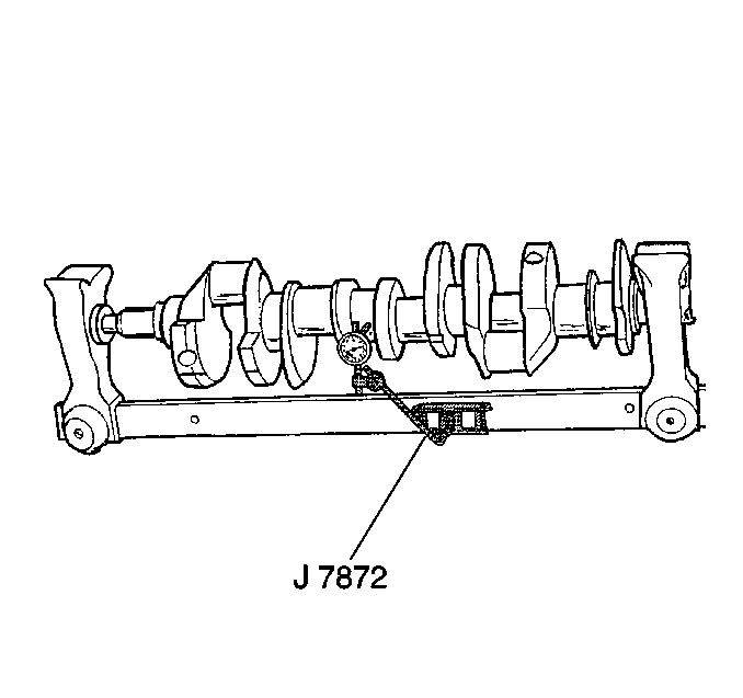
- Using wooden V blocks,
support the crankshaft on the front and rear journals.
- Use the J 7872
in order to measure the crankshaft runout at the front and rear intermediate
journals. Refer to
Engine Mechanical Specifications
.
- Use the J 7872
in order to measure the runout of the crankshaft rear flange. Refer to Engine
Mechanical Specifications.
Replace or repair the crankshaft if the measurements are not within
specifications.
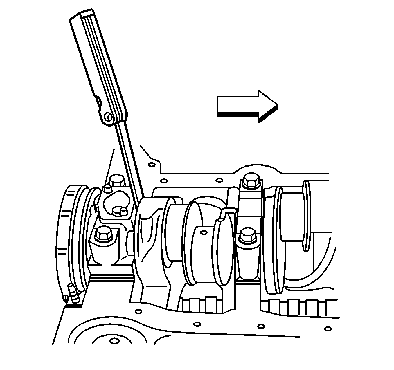
- In order to properly measure
the crankshaft end play, the crankshaft, the crankshaft bearings, the crankshaft
bearing caps, and the fasteners must be installed into the engine block
and the bolts and studs tightened to specifications.
| 15.1. | Firmly thrust the end of the crankshaft first rearward then forward.
This will line up the rear crankshaft bearing and the crankshaft thrust surfaces. |
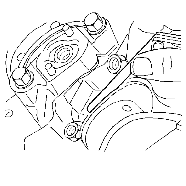
| 15.2. | With the crankshaft pushed forward, insert a feeler gauge between
the crankshaft and the crankshaft bearing surface and then measure the clearance.
Refer to
Engine Mechanical Specifications
. |
| 15.3. | If the correct end play cannot be obtained, verify that the correct
size crankshaft bearing has been installed. |
| 15.4. | Inspect the crankshaft for binding. Turn the crankshaft to check
for binding. If the crankshaft does not turn freely, loosen the crankshaft
bearing bolts and studs, one crankshaft bearing cap at a time, until the
tight crankshaft bearing is located. |
Burrs on the crankshaft bearing cap, foreign matter between the crankshaft
bearing and the engine block or the crankshaft bearing cap, or a faulty crankshaft
bearing could cause a lack of clearance at the crankshaft bearing.
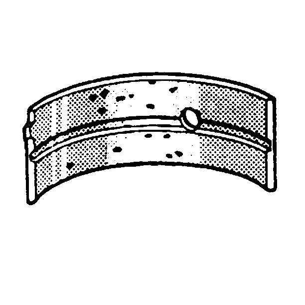
- Inspect the crankshaft
bearings for craters or pockets. Flattened sections on the crankshaft bearing
halves also indicate fatigue.
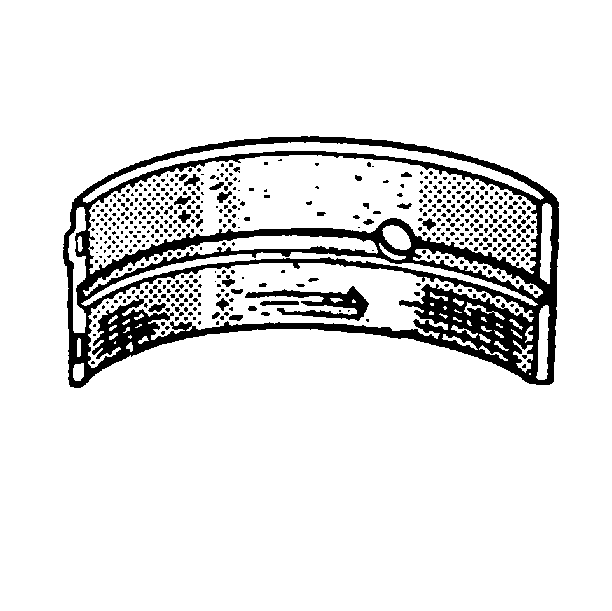
- Inspect the crankshaft
bearings for excessive scoring or discoloration.
- Inspect the crankshaft bearings for dirt or debris imbedded into
the crankshaft bearing material.
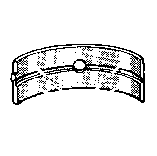
- Inspect the crankshaft
bearings for improper seating indicated by bright, polished sections of the
bearing.
If the lower half of the bearing is worn or damaged, both the upper
and lower halves of the crankshaft bearing should be replaced.
Generally, if the lower half of the crankshaft bearing is suitable for
use, the upper half of the crankshaft bearing should also be suitable for
use.
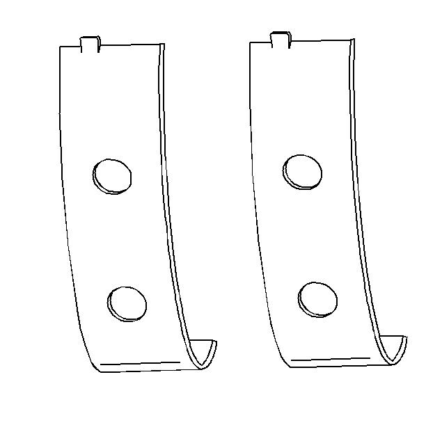
Important: If cracks, severe gouges or burned spots are found, the crankshaft must
be replaced. Slight roughness may be removed with a fine polishing cloth soaked
in clean engine oil. Burrs may be removed with a fine oil stone.
- Inspect the crankshaft bearing journals and the crankshaft thrust surfaces
for the following conditions:
| • | Overheating (discoloration) |
- Inspect the corresponding crankshaft bearings for embedded foreign
material and determine the source.
Important: Note the location of the crankshaft main bearing high spots. If they
are not in line, the crankshaft is bent and must be replaced.
- Inspect the crankshaft bearings for uneven side-to-side wear. This may
indicate a bent crankshaft or a tapered bearing journal.
Notice: Do not scrape, shim, or file bearing inserts. If the bearing surface
of the insert is touched with bare fingers, the skin oil and acids will etch
the bearing surface.
Important: The crankshaft bearings are of the precision insert type. The crankshaft
bearings are available in standard and various undersizes.
- Inspect the outer surfaces of the crankshaft bearings for the following
conditions:
| • | Wear - surface wear indicates either movement of the insert or
high spots in the surrounding material (spot wear). |
| • | Overheating or discoloration |
| • | Looseness or rotation indicated by flattened tangs and wear grooves |
- Inspect the thrust surfaces of the main thrust bearing for the
following conditions:
| • | Grooving (Grooves are caused by irregularities of the crankshaft
thrust surface.) |
Important: If crankshaft bearing failure is due to other than normal wear, investigate
the cause. Inspect the crankshaft or connecting rod bearing bores.
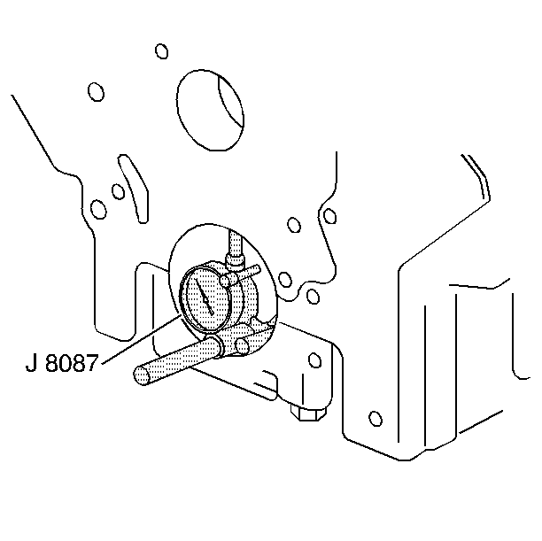
- Inspect the connecting rod bearing bores or crankshaft main bearing
bores using the following procedure:
| 25.1. | Tighten the bearing cap to specification. |
| 25.2. | Measure the bearing bore for taper and out-of-round using the J 8087
. No taper or out-of-round
should exist. |
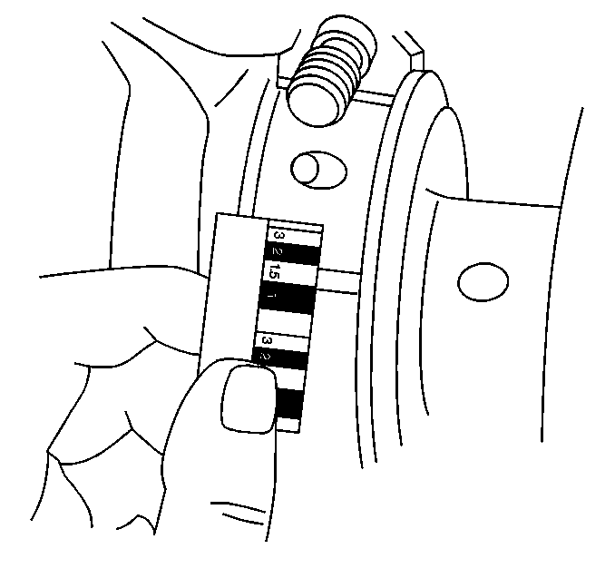
Measure the bearing clearance to determine the correct replacement bearing
insert size. There are two methods to measure bearing clearance. Micrometer
method gives more reliable results and is preferred.
Micrometer method yields measurement from which the bearing clearance
can be computed.
Plastic gauge method yields the bearing clearance directly.
Plastic gauge method does not give any indication of bearing run-out.


