Refer to
Power, Ground, and Injectors
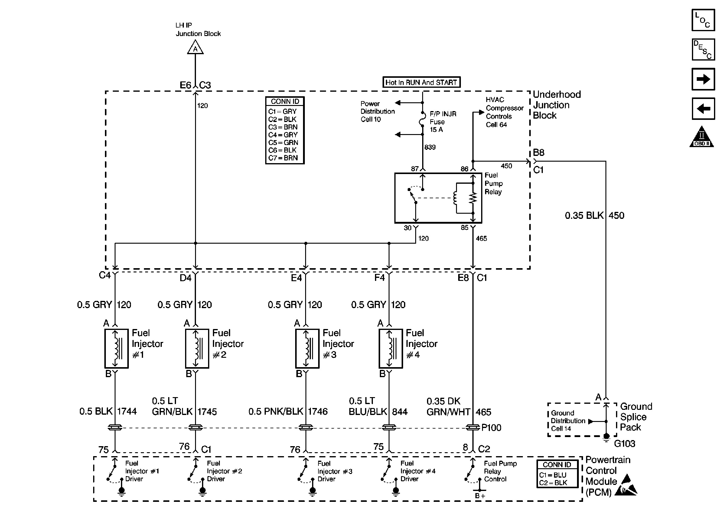
.
Circuit Description
The Powertrain Control Module(PCM) controls the fuel injectors by using a ground circuit driver within the PCM. If a electrical malfunction occurs in the fuel injector circuit, a DTC will set.
Conditions for Running the DTC
| • | The engine is running |
| • | The battery voltage is more than 9 volts. |
Conditions for Setting the DTC
| • | The injector current is less than 1 amp, |
| OR: |
| the injector current is continuously high. |
| • | The above conditions are met for 7 seconds. |
Action Taken When the DTC Sets
| • | The Malfunction Indicator Lamp (MIL) illuminates. |
| • | The PCM records the operating conditions at the time when the diagnostic fails. This information stores in the Freeze Frame and Failure Records buffers. |
| • | A history DTC stores. |
| • | The coolant fan turns on. |
Conditions for Clearing the DTC
| • | The MIL will turn off after 3 consecutive ignition cycles in which the diagnostic runs without a fault. |
| • | A history DTC will clear after 40 consecutive warm up cycles without a fault. |
| • | Use a scan tool to clear the DTCs. |
Diagnostic Aids
A fuel injector driver circuit that is open or shorted to voltage will cause the DTC to set and will also cause a misfire due to an inoperative fuel injector. A misfire DTC should also set indicating which cylinder is inoperative.
The long term fuel trims and the short term fuel trims that are excessively high or low are a good indication that a fuel injector is malfunctioning.
A poor connection may be cleaned when disconnecting and reconnecting the connector. If the malfunction is not present after the connector is disconnected and reconnected, inspect the connector for the following conditions:
| • | Any corrosion |
| • | An incorrect terminal tension |
Test Description
The numbers below refer to step numbers on the diagnostic table.
-
This step tests the harness wiring and the PCM control of the fuel injector with the fuel injector test lamp. If the test lamp blinks, the PCM and the wiring to the fuel injector are OK. The Fuel Inj Coil Test - ECT Between 10-35 Degrees and Fuel Inj Coil Test - ECT Outside 10-35 Degrees diagnostics will determine if the fuel injectors are malfunctioning.
-
The replacement PCM must be programmed and the Crankshaft Position System Variation Learn procedure must be performed.
Step | Action | Values | Yes | No | ||||
|---|---|---|---|---|---|---|---|---|
1 | Did you perform the Powertrain On-Board Diagnostic (OBD) System Check? | -- | Go to Step 2 | |||||
2 | Attempt to start the engine. Does the engine start and run? | -- | Go to Step 3 | |||||
Does the fuel injector test lamp blink? | -- | Go to Fuel Injector Solenoid Coil Test - Engine Coolant Temperature Between 10-35 Degrees C (50-95 Degrees F) or Fuel Injector Solenoid Coil Test - Engine Coolant Temperature Outside 10-35 Degrees C (50-95 Degrees F) | Go to Step 4 | |||||
4 | Did the fuel injector test lamp stay on steady when cranking the engine? | -- | Go to Step 5 | Go to Step 7 | ||||
5 |
Notice: Do not insert test equipment probes (DVOM etc.) into any connector or fuse block terminal. The diameter of the test probes will deform most terminals. A deformed terminal will cause a poor connection, which will result in a system failure. Always use the J-35616 GM-Approved Terminal Test Kit in order to front probe terminals. Do not use paper clips or other substitutes to probe terminals. When using the J-35616 GM-Approved Terminal Test Kit, ensure the terminal test adapter choice is the correct size for the connector terminal. Do not visually choose the terminal test adapter because some connector terminal cavities may appear larger than the actual terminal in the cavity. Using a larger terminal test adapter will damage the terminal. Refer to the J-35616 GM-Approved Terminal Test Kit label on the inside of the J-35616 GM-Approved Terminal Test Kit for the correct adapter along with the connector end view for terminal size.Does the test lamp illuminate? | -- | Go to Step 6 | Go to Step 12 | ||||
6 | Repair the short to ground in the Driver circuit. Refer to Wiring Repairs in Wiring Systems. Did you complete the repair? | -- | Go to Step 13 | -- | ||||
7 |
Notice: Do not insert test equipment probes (DVOM etc.) into any connector or fuse block terminal. The diameter of the test probes will deform most terminals. A deformed terminal will cause a poor connection, which will result in a system failure. Always use the J-35616 GM-Approved Terminal Test Kit in order to front probe terminals. Do not use paper clips or other substitutes to probe terminals. When using the J-35616 GM-Approved Terminal Test Kit, ensure the terminal test adapter choice is the correct size for the connector terminal. Do not visually choose the terminal test adapter because some connector terminal cavities may appear larger than the actual terminal in the cavity. Using a larger terminal test adapter will damage the terminal. Refer to the J-35616 GM-Approved Terminal Test Kit label on the inside of the J-35616 GM-Approved Terminal Test Kit for the correct adapter along with the connector end view for terminal size.Does the test lamp illuminate? | -- | Go to Step 8 | Go to Step 9 | ||||
8 |
Notice: Do not insert test equipment probes (DVOM etc.) into any connector or fuse block terminal. The diameter of the test probes will deform most terminals. A deformed terminal will cause a poor connection, which will result in a system failure. Always use the J-35616 GM-Approved Terminal Test Kit in order to front probe terminals. Do not use paper clips or other substitutes to probe terminals. When using the J-35616 GM-Approved Terminal Test Kit, ensure the terminal test adapter choice is the correct size for the connector terminal. Do not visually choose the terminal test adapter because some connector terminal cavities may appear larger than the actual terminal in the cavity. Using a larger terminal test adapter will damage the terminal. Refer to the J-35616 GM-Approved Terminal Test Kit label on the inside of the J-35616 GM-Approved Terminal Test Kit for the correct adapter along with the connector end view for terminal size.Does the test lamp illuminate? | -- | Go to Step 11 | Go to Step 10 | ||||
9 |
Did you complete the repair? | -- | Go to Step 13 | -- | ||||
10 |
Did you find and correct the condition? | -- | Go to Step 13 | Go to Step 12 | ||||
11 |
Did you complete the repair? | -- | Go to Step 13 | Go to Step 12 | ||||
|
Important:: The replacement PCM must be programmed. Refer to Powertrain Control Module Replacement/Programming . Replace the PCM. Refer to Powertrain Control Module Replacement . Did you complete the repair? | -- | Go to Step 13 | -- | |||||
13 |
Does the DTC reset? | -- | Go to Step 2 | System OK |
