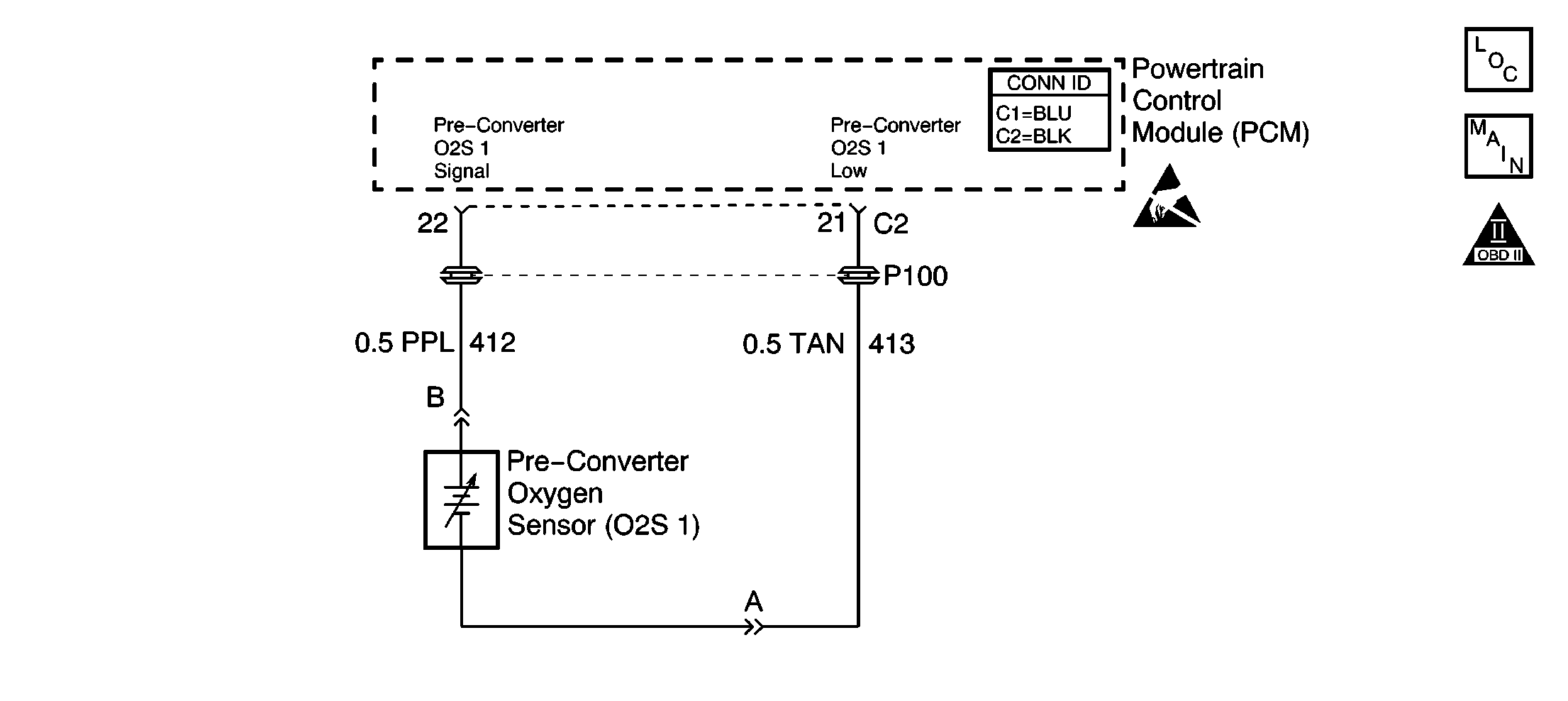
Circuit Description
The Powertrain Control Module (PCM) continuously monitors the oxygen sensor 1 (O2S 1) activity for 100 seconds. During the monitor period, the PCM counts the number of times that the O2S 1 switches from rich to lean and from lean to rich. If the number of switches is too low, a DTC P1133 will set.
Conditions For Running The DTC
| • | The following DTCs are not set: P0105, P0107, P0108, P0112, P0113, P0117, P0118, P0122, P0123, P0171, P0201, P0202, P0203, P0204, P0300, P0335, P0440, P0442, P0446, P0506, P0507, P0601, P0602, or P1441. |
| • | The engine coolant temperature (ECT) is more than 75°C (167°F). |
| • | The engine speed is between 1800 and 2300 RPM. |
| • | The engine operating in closed loop. |
| • | The throttle position (TP) angle is between 8 percent and 15 percent. |
| • | The evaporative emissions (EVAP) control system is commanded open for more than 80 percent. |
| • | The purge learned memory is more than approximately 0.86. |
| • | The diagnostic completes when 30 seconds of accumulated time has been spent in the above conditions. |
Conditions for Setting the DTC
The number of rich to lean counts is less than 1 or the lean to rich counts is less than 1.
Action Taken When the DTC Sets
| • | The malfunction indicator lamp (MIL) will illuminate after 2 consecutive ignition cycles in which the diagnostic runs with the malfunction present. |
| • | The PCM will record the operating conditions at the time that the diagnostic fails. This information will store in the Freeze Frame and Failure Records buffers. |
| • | A history DTC stores. |
Conditions for Clearing the MIL/DTC
| • | The MIL will turn off after 3 consecutive ignition cycles in which the diagnostic runs without a fault. |
| • | A history DTC will clear after 40 consecutive warm up cycles without a fault. |
| • | Use a scan tool to clear the DTCs. |
Diagnostic Aids
DTC P1133 is most likely caused by one of the following conditions:
| • | The fuel system will go rich if the fuel pressure is too high. The PCM can compensate for some increase. If the fuel pressure becomes too high, a DTC P0132 will be set. Refer to Fuel System Diagnosis . |
| • | A leaking or malfunctioning fuel injector can cause the system to go rich. |
| • | A manifold absolute pressure (MAP) output that causes the PCM to sense a higher than normal manifold pressure (low vacuum) can cause the system to go rich. Disconnecting the MAP sensor will allow the PCM to set a fixed value for the MAP sensor. Substitute a different MAP sensor if the rich condition disappears while the sensor is disconnected. |
| • | An intermittent TP sensor output will cause the system to go rich due to a false indication of the engine accelerating. |
| • | Inspect the O2S 1 for silicone contamination from fuel or use of improper RTV sealant. The sensor may have a white powdery coating which results in a high but false voltage signal (rich exhaust indication). The PCM will then reduce the amount of fuel delivered to the engine causing a severe surge or driveability problem. |
Test Description
The number below refers to step number on the diagnostic table.
Step | Action | Values | Yes | No | ||||
|---|---|---|---|---|---|---|---|---|
1 | Did you perform the Powertrain On Board Diagnostic (OBD) System Check? | -- | Go to Step 2 | |||||
2 |
Do the transitions read less than the specified values? | 1-1 | Go to Step 3 | Go to Diagnostic Aids | ||||
3 |
Did you find and correct any of these conditions? | -- | Go to Step 13 | Go to Step 4 | ||||
4 |
Caution: Avoid contact with moving parts and hot surfaces while working around a running engine in order to prevent physical injury. Did you find and correct a condition? | -- | Go to Step 13 | Go to Step 5 | ||||
5 |
Is the voltage within the specified range? | 407-509 mV | Go to Step 6 | Go to Step 8 | ||||
6 | Connect a jumper wire between the O2S 1 signal circuit and ground at the connector. Is the voltage less than the specified value? | 200 mV | Go to Step 7 | Go to Step 9 | ||||
7 |
Notice: Determine and correct the cause of the contamination in order to prevent damage to the replacement sensors. Caution: Avoid contact with moving parts and hot surfaces while working around a running engine in order to prevent physical injury. Did you complete the repair? | Go to Step 13 | -- | |||||
8 |
Did you complete the repair? | -- | Go to Step 13 | -- | ||||
9 |
Is voltage more than the specified value? | 407 mV | Go to Step 10 | Go to Step 11 | ||||
10 |
Did you find and correct the condition? | 5 ohms | Go to Step 13 | Go to Step 12 | ||||
11 |
Did you find and correct the condition? | 5 ohms | Go to Step 13 | Go to Step 12 | ||||
|
Important:: The replacement PCM must be programmed. Refer to Powertrain Control Module Replacement/Programming . Replace the PCM. Refer to Powertrain Control Module Replacement . Did you complete the repair? | -- | Go to Step 13 | -- | |||||
13 |
Does the DTC reset? | -- | Go to Step 2 | System OK |
