Engine Coolant Temperature (ECT) Sensor
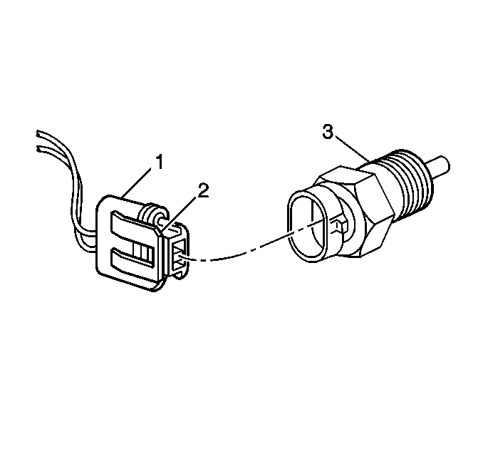
The engine coolant temperature (ECT) sensor (3) is a thermistor, a resistor which changes value based on temperature, mounted in the engine coolant stream. A low coolant temperature produces a high resistance of 100,000 ohms at -40°C (-40°F), while a high temperature causes a low resistance of 70 ohms at 130°C (266°F).
The PCM supplies a 5 volt signal to the ECT sensor through a resistor in the PCM and monitors the terminal voltage. Since this forms a series circuit to ground through the ECT sensor, high sensor resistance will result in high PCM terminal voltage. When the resistance of the ECT sensor is low, the terminal voltage will be drawn lower. This terminal voltage indicates engine coolant temperature to the PCM.
A hard fault in the ECT sensor circuit should set either a DTC P0117 or P0118. Remember, these DTCs indicate a malfunction in the engine coolant temperature circuit, so proper use of the DTC table may lead to either repairing a wiring problem or replacing the sensor, to properly repair a problem.
Intake Air Temperature (IAT) Sensor
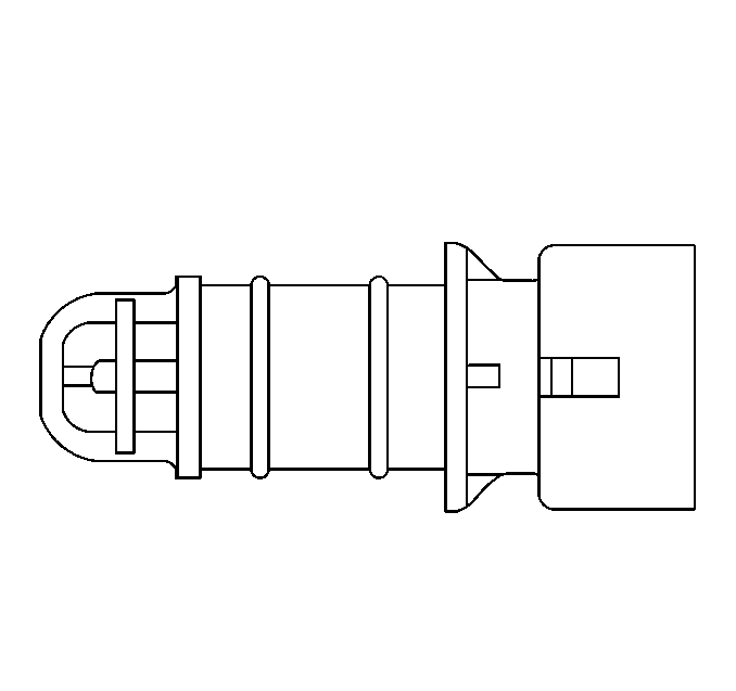
The intake air temperature (IAT) sensor is a thermistor, a resistor which changes value based on the temperature of air entering the engine, similar to the ECT sensor. A low temperature produces a high resistance of 100,000 ohms at -40°C (-40°F) while a high temperature causes low resistance of 70 ohms at 130°C (266°F). The PCM supplies a 5 volt signal to the IAT sensor through a resistor in the PCM and monitors the terminal voltage. The voltage will be high when the intake air is cold, and low when the intake air is hot. By measuring the voltage, the PCM knows the intake air temperature. This input is used in starting and running fuel control calculations.
A fault in the IAT sensor circuit should set either a DTC P0112 or DTC P0113.
Oxygen Sensor (O2S 1)
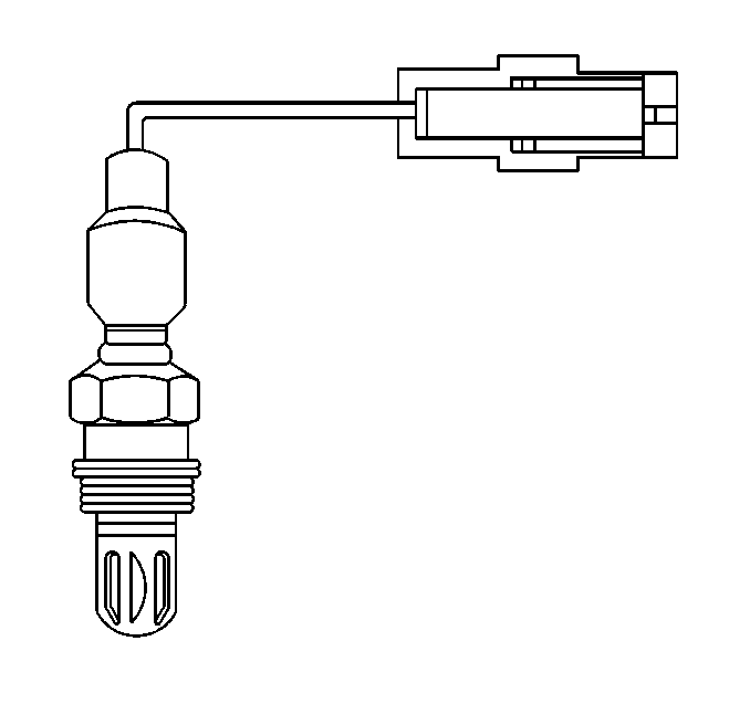
The oxygen sensor (O2S 1) is mounted in the exhaust system where it can monitor the oxygen content of the exhaust gas stream. The oxygen content in the exhaust reacts with the sensor to produce a voltage output. This voltage ranges from approximately 0.1 volt at a high oxygen lean mixture) to 0.9 volt at a low oxygen rich mixture. This voltage can be measured with a scan tool.
By monitoring the voltage output of the O2S 1, the PCM will know what fuel mixture command to give to the injectors.
| • | Lean mixture--low O2S 1 voltage = rich command |
| • | Rich mixture--high O2S 1 voltage = lean command |
The O2S 1, if open, should set a DTC P0134. A constant low voltage in the sensor circuit should set a DTC P0131. A constant high voltage in the circuit should set a DTC P0132. DTCs P0131 and P0132 could also be set as a result of fuel system problems. See the DTC tables for conditions that can cause a lean or rich system.
Rear Heated Oxygen Sensor (HO2S 2)
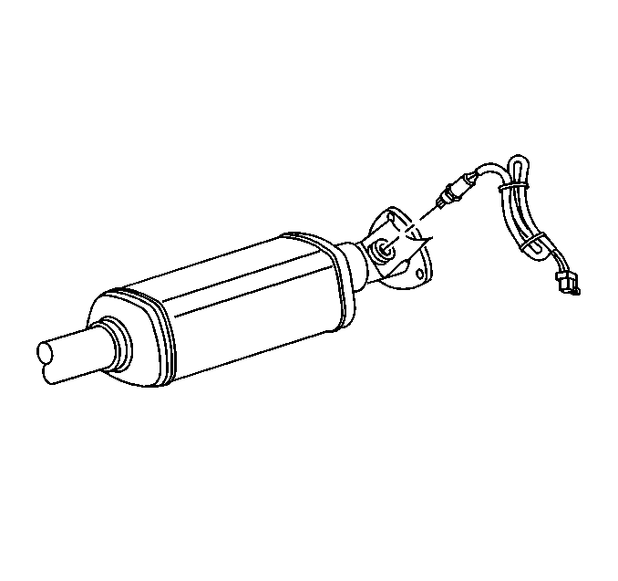
The rear heated oxygen sensor (HO2S 2) is used to monitor the oxygen storage capability of the catalytic converter. Similar to the O2S 1, the HO2S 2 reacts with the oxygen content in the exhaust stream to produce a voltage signal, only after the catalytic converter. This voltage ranges from approximately 0.1 volt at a high oxygen lean mixture, to 0.9 volt at a low oxygen rich mixture. Unlike the O2S 1, with a good catalytic converter, the HO2S 2 is normal when its activity appears lazy or inactive. The PCM compares readings from both the front O2S 1 and the HO2S 2 to determine the catalyst efficiency and will illuminate the MIL if this efficiency falls below a calibrated level.
Throttle Position (TP) Sensor
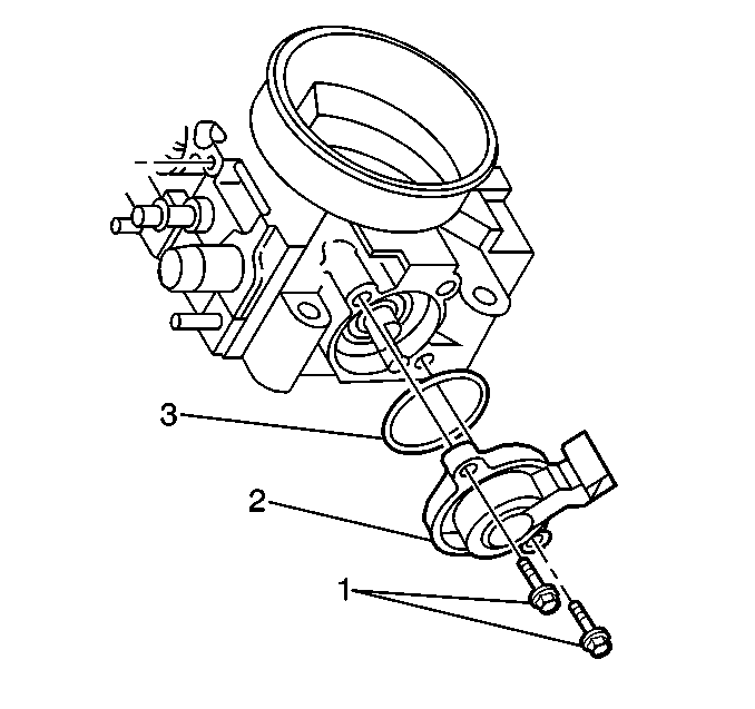
The throttle position (TP) sensor (2) is a potentiometer connected to the throttle shaft on the throttle body. The TP sensor electrical circuit consists of a 5 volt supply line and a ground line, both provided by the powertrain control module (PCM), and a signal line to the PCM. By monitoring the voltage on this signal line, the PCM can calculate the throttle position angle as a percentage. As the throttle valve angle is changed as the accelerator pedal is moved, the output of the TP sensor also changes. At a closed throttle position, the output of the TP sensor is approximately 0.6 volt. As the throttle valve opens, the output increases so that, at wide open throttle, the output voltage should be near 5 volts.
The PCM can determine fuel delivery based upon the throttle valve angle. A broken or loose TP sensor can cause intermittent bursts of fuel from the injectors and an unstable idle, because the PCM thinks the throttle is moving. A high or low voltage problem in the TP sensor circuits should set either a DTC P0122 or DTC P0123. The PCM also has the capability of setting a DTC P0121 if the sensor is reading out of range. Once a diagnostic trouble code is set, the PCM will use a default value for the TP sensor, and some vehicle performance will return.
See the Throttle Position Sensor Replacement portion of the service manual for the replacement of the TP sensor. The TP sensor is not adjustable.
Manifold Absolute Pressure (MAP) Sensor
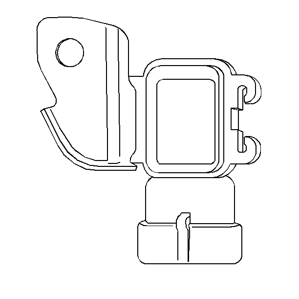
The Manifold Absolute Pressure (MAP) sensor measures the changes in the intake manifold pressure which result from engine load and speed changes, and converts this measurement into a voltage output.
The PCM sends a 5 volt reference signal to the MAP sensor. As the manifold pressure changes, the electrical resistance of the sensor also changes. By monitoring the sensor output voltage, the PCM can determine the manifold pressure. A higher pressure, low vacuum requires more fuel, while a lower pressure, higher vacuum requires less fuel.
A closed throttle on when the engine is decelerating would produce a relatively low MAP output, while a wide open throttle would produce a high output. The manifold absolute pressure is the opposite of what you would measure on a vacuum gage. When manifold pressure is high, the vacuum is low. The MAP sensor is also used to measure barometric pressure under certain conditions, which allows the PCM to automatically adjust for different altitudes.
A high or low voltage fault in the MAP sensor circuit should set a DTC P0107 or DTC P0108. If the MAP sensor sends an intermittent zero voltage signal to the PCM, a DTC P0106 will set.
Vehicle Speed Sensor (VSS)
The vehicle speed sensor (VSS) is a permanent magnetic generator in the transaxle which sends an AC voltage signal to the PCM, which the PCM converts to kilometers per hour (km/h) and miles per hour (MPH). There are several different types of vehicle speed sensors. Refer to Diagnostic Starting Point - Automatic Transmission in Automatic Transmission.
Knock Sensor (KS)
The knock sensor (KS) detects abnormal spark knocking in the engine. The sensor is mounted in the engine block near the cylinders. The sensor produces an AC output voltage which increases with the severity of the knock. This signal voltage is sent to the PCM. The PCM then adjusts the ignition control (IC) timing to reduce the spark knock.
A malfunction in the KS circuit or module will set a DTC P0325.
A/C Refrigerant Pressure Sensor
The A/C refrigerant pressure sensor provides a signal to the PCM which indicates varying high side refrigerant pressure between approximately 0 psi and 450 psi.
The PCM uses this input in order to determine the A/C compressor load on the engine in order to help control idle speed with the IAC valve.
The A/C refrigerant pressure sensor circuit consists of a 5 volt reference line and a ground line, both provided by the PCM, and a signal line to the PCM. The signal is a voltage that varies from approximately 0.1 volt at 0 psi, to 4.9 volts at 450 psi or more. A problem in the A/C refrigerant pressure circuits or sensor may set a DTC P0530 and will make the A/C compressor inoperative.
Crankshaft Position (CKP) Sensor
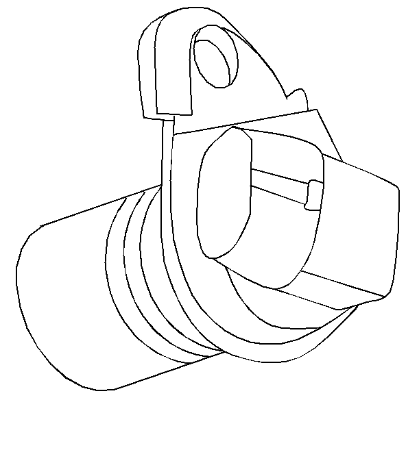
The crankshaft position (CKP) sensor provides a signal to the electronic ignition control module (ICM), which the PCM uses as a reference to calculate RPM and crankshaft position. A fault in the CKP sensor circuits will cause a DTC P0335.
Important: A Crankshaft Position System Variation Learn procedure must be performed any time a change is made to the crankshaft sensor to crankshaft relationship. Changing the crankshaft sensor to crankshaft relationship will not allow the PCM to detect misfire at all speeds and loads accurately, resulting in a possible false misfire DTC being set. Removing a part for inspection and then reinstalling the same part is considered a disturbance. A false DTC P0300 could be set if this procedure is not performed. Refer to Crankshaft Position System Variation Learn .
Camshaft Position (CMP) Sensor
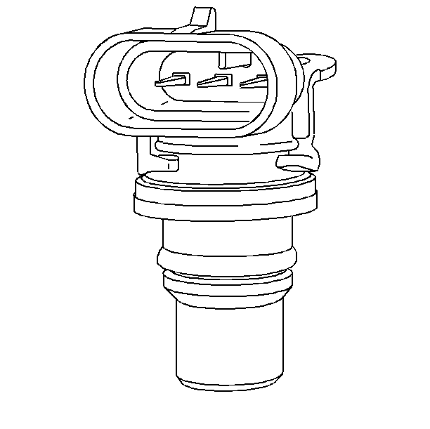
The camshaft position (CMP) sensor is used to correlate crankshaft to camshaft position so that the PCM can determine which cylinder is ready to be fueled by the fuel injector. The CMP sensor is also used to determine which cylinder is misfiring when misfire is present. If the PCM receives an intermittent signal from the CMP, then the CMP Resync Counter will increment. When the PCM cannot use the information from the CMP sensor, a DTC is set and the PCM will fuel the engine using the alternating synchronous double fire (ASDF) method. This sensor has no effect on the electronic ignition system.
A malfunction in the CMP sensor circuits will cause a DTC P0341 or P0342.
Fuel Tank Pressure Sensor
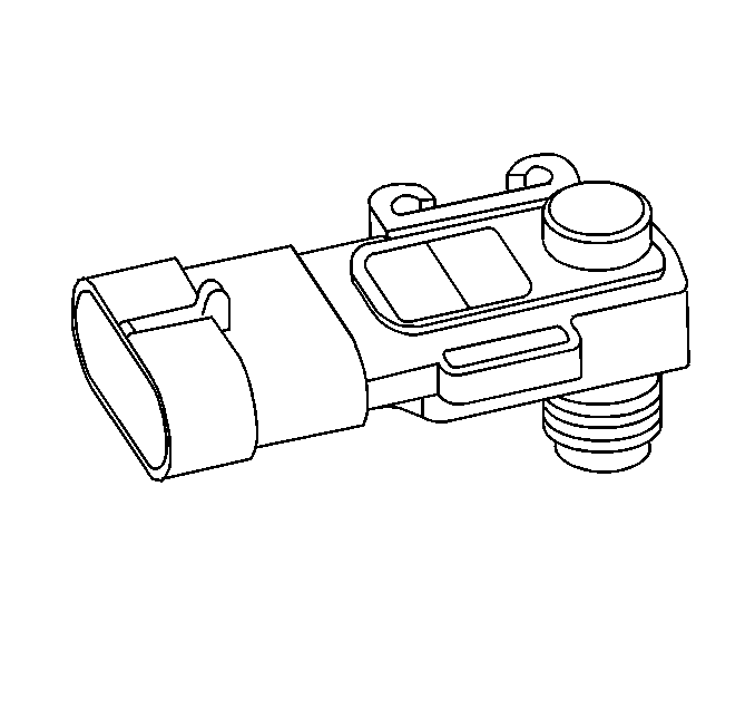
The fuel tank pressure sensor is similar to the manifold absolute pressure (MAP) sensor. The sensor is used to measure the difference between the air pressure, or vacuum, in the fuel tank and the outside air pressure. The PCM supplies a 5 volt reference and a ground to the sensor and the sensor sends a voltage signal between 0.1 and 4.9 volts back to the PCM. When the air pressure in the fuel tank is equal to the outside air pressure, as when the fuel cap is removed, the output voltage of the sensor will be from 1.3 to 1.7 volts.
Fuel Level Sensor
The fuel sensor is attached to the modular fuel sender. The resistance of the fuel sensor changes with the fuel level by means of a rheostat. As the position of the float varies with the fuel level, the rheostat produces a variable resistance. The PCM converts this variable resistance into the fuel level reading displayed on the instrument panel.
The resistance value is sent to the PCM and then sent to the instrument panel cluster (IPC) and displayed on the fuel gauge.
