Cylinder Head Replacement Front
Special Tools
J 36660-A
Torque Angle Meter
Removal Procedure
Important: During disassembly, keep the valve train components together and identified in order to install the parts in the original locations.
Perform a compression test. Refer to
Engine Compression Test
. Record the results before you perform the following repairs:
| • | Remove the cylinder heads. |
| • | Disassemble the valve mechanism. |
Caution: Unless directed otherwise, the ignition and start switch must be in the OFF or LOCK position, and all electrical loads must be OFF before servicing
any electrical component. Disconnect the negative battery cable to prevent an electrical spark should a tool or equipment come in contact with an exposed electrical terminal. Failure to follow these precautions may result in personal injury and/or damage to
the vehicle or its components.
- Disconnect the negative battery cable.
- Depressurize the fuel system. Refer to
Throttle Body Assembly Replacement
for the 3.4L engine.
- Drain the cooling system. Recover the cooling system. Refer to
Cooling System Draining and Filling
.
- Remove the top half of the air cleaner assembly. Refer to
Air Cleaner Assembly Replacement
for the 3.4L engine.
- Remove the throttle body duct.
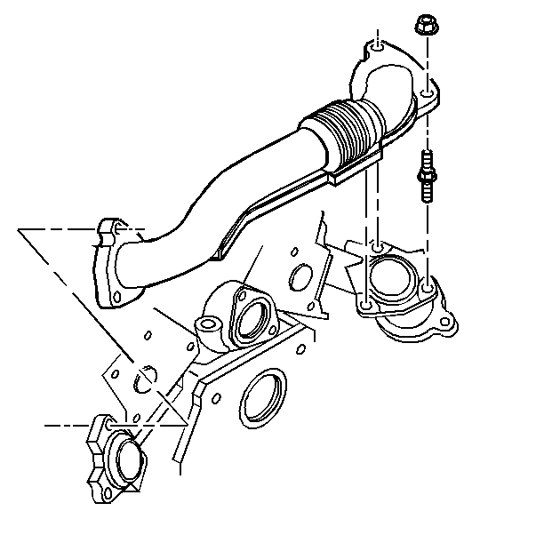
- Remove the exhaust crossover. Refer to
Exhaust Crossover Replacement
.
- Remove the exhaust crossover.
- Remove the valve rocker arms and pushrods. Refer to
Valve Rocker Arm and Push Rod Replacement
.
- Remove the front exhaust manifold. Refer to
Exhaust Crossover Replacement
.

- Remove and discard the cylinder head bolts.
- Remove the cylinder head.
- Clean the mating surfaces of the following items:
- Clean the cylinder block bolt threads.
Installation Procedure

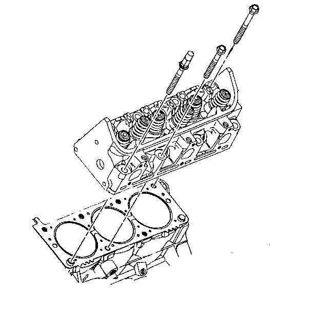
- Place the cylinder head gasket into position over the dowel pins. Ensure that the THIS SIDE UP note is showing.
- Install the cylinder head.
Notice: Refer to Fastener Notice in the Preface section.

Notice: This component uses torque-to-yield bolts. When servicing this component
do not reuse the bolts, New torque-to-yield bolts must be installed. Reusing
used torque-to-yield bolts will not provide proper bolt torque
and clamp load. Failure to install NEW torque-to-yield bolts may lead to engine
damage.
- Install the NEW cylinder head bolts.
Tighten
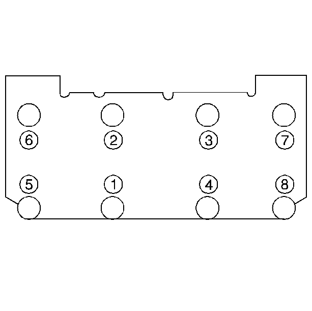
Tighten the bolts to 60 N·m (44 lb ft) in the sequence shown. Use the
J 36660-A
in order to tighten the bolts an additional 95 degrees.
- Install the intake gasket.
- Refer to
Valve Rocker Arm and Push Rod Replacement
when you perform the following steps in order to install the pushrods that are loosely retained by the rocker arms:
| 5.2. | Coat the pushrod ends with prelube. |
Use GM P/N 1052356 or an equivalent.
| 5.3. | The intake pushrods are identified with yellow stripes. The intake pushrods are 14.6 cm (5.75 in) long. |
| 5.4. | The exhaust pushrods are identified with green stripes. The exhaust pushrods are 15.24 cm (6 in) long. |
| 5.5. | Ensure that the pushrods seat in the lifter. |
- Install the rocker arm bolts. Refer to
Valve Rocker Arm and Push Rod Replacement
.
- Install the upper and the lower intake manifolds. Refer to
Intake Manifold Replacement
.
- Install the valve rocker cover. Refer to
Valve Rocker Arm Cover Replacement
.
- Install the left exhaust manifold. Refer to
Exhaust Manifold Replacement
.

- Install the crossover pipe. Refer to
Exhaust Crossover Replacement
.

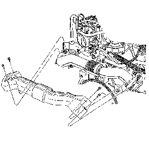
- Install the crossover heat shield.
- Fill the cooling system. Refer to
Cooling System Draining and Filling
.
- Install the throttle body duct. Refer to
Air Cleaner Assembly Replacement
for the 3.4L engine.
Install the top half of the air cleaner assembly.
- Connect the negative battery cable.
Cylinder Head Replacement Rear
Special Tools
J 36660-A
Torque Angle Meter
Removal Procedure
Important: During disassembly, keep the valve train components together and identified in order to install the components in their original locations.
Perform a compression test. Refer to
Oil Pressure Diagnosis and Testing
. Record the results before you perform the following repairs:
| • | Remove the cylinder heads. |
| • | Disassemble the valve mechanism. |
Caution: Unless directed otherwise, the ignition and start switch must be in the OFF or LOCK position, and all electrical loads must be OFF before servicing
any electrical component. Disconnect the negative battery cable to prevent an electrical spark should a tool or equipment come in contact with an exposed electrical terminal. Failure to follow these precautions may result in personal injury and/or damage to
the vehicle or its components.
- Disconnect the negative battery cable.
- Depressurize the fuel system. Refer to
Fuel Pressure Relief
for the 3.4L engine.
- Drain the cooling system. Recover the cooling system. Refer to
Cooling System Draining and Filling
.
- Remove the exhaust crossover pipe. Refer to
Exhaust Crossover Replacement
.
- Raise the support the vehicle. Refer to
Lifting and Jacking the Vehicle
.
- Remove the right exhaust manifold. Refer to
Exhaust Manifold Replacement
.
- Lower the vehicle.
- Remove the pushrods. Remove the rocker arms. Refer to
Valve Rocker Arm and Push Rod Replacement
.

- Remove and discard the cylinder head bolts.
- Remove the cylinder head.
- Clean the mating surfaces on the following items:
- Clean the cylinder block bolt threads.
Installation Procedure

- Place the cylinder head gasket in position over the dowel pins. Ensure that the THIS SIDE UP note is showing.
- Install the cylinder head.
Notice: Refer to Fastener Notice in the Preface section.

Notice: This component uses torque-to-yield bolts. When servicing this component
do not reuse the bolts, New torque-to-yield bolts must be installed. Reusing
used torque-to-yield bolts will not provide proper bolt torque
and clamp load. Failure to install NEW torque-to-yield bolts may lead to engine
damage.
- Install the NEW cylinder head bolts.
Tighten
Tighten the bolts to 60 N·m (44 lb ft) in the sequence shown. Use the
J 36660-A
in order to tighten the bolts an additional 95 degrees.
- Install the intake gasket.
- Install the rocker arm bolts and the pushrods. Refer to
Valve Rocker Arm and Push Rod Replacement
.
- Install the intake manifold. Refer to
Intake Manifold Replacement
.
- Install the valve rocker cover. Refer to
Valve Rocker Arm Cover Replacement
.
- Install the spark plug wires to the cylinder head. Refer to
Spark Plug Wire Harness Replacement
.
- Raise and support the vehicle. Refer to
Lifting and Jacking the Vehicle
.
- Install the right exhaust manifold. Refer to
Exhaust Manifold Replacement
.
- Lower the vehicle.

- Install the exhaust crossover pipe. Refer to
Exhaust Crossover Replacement
.

- Install the crossover heat shield.
- Fill the cooling system. Refer to
Cooling System Draining and Filling


