Water Pump Replacement 2.4 L
Removal Procedure
- Disconnect the negative battery cable.
- Drain the coolant. Recover the coolant. Refer to Cooling System Draining and Filling .
- Disconnect the electrical connectors.
- Remove the exhaust manifold heat shield.
- Remove the heat wrap from the heater hose.
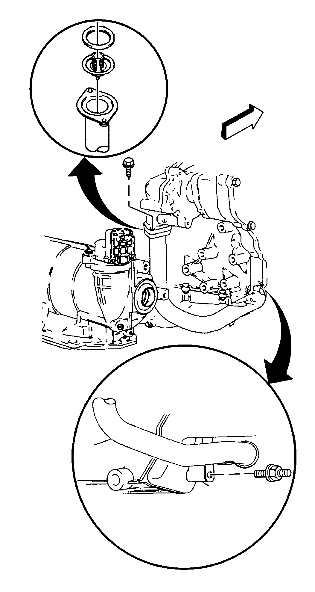
- Remove the coolant inlet housing bolt through the exhaust manifold.
- Raise the vehicle. Refer to Lifting and Jacking the Vehicle in General Information.
- Remove the exhaust manifold brace-to-manifold bolt.
- Remove the manifold-to-exhaust pipe studs.
- Remove the heater outlet pipe bracket-to-transmission bolt.
- Remove the coolant inlet housing assembly- to-water pump cover bolt.
- Disconnect the exhaust pipe from the exhaust manifold. Refer to Catalytic Converter Replacement in Engine Exhaust.
- Pull down and back on the exhaust manifold pipe in order to disengage the pipe from the exhaust manifold.
- Disconnect the coolant inlet pipe from the oil pan. Remove the pipe.
- Lower the vehicle.
- Remove the brake vacuum pipe from the cam housing.
- Remove the exhaust manifold to cylinder head retaining nuts.
- Remove the exhaust manifold.
- Remove the seals and the gaskets of the exhaust manifold.
- Disconnect the heater hose quick connect from the heater outlet pipe.
- Remove the front timing chain cover. Refer to Timing Chain Housing Replacement in Engine Mechanical - 2.4L.
- Remove the timing chain tensioner. Refer to Camshaft Timing Chain, Sprocket, and Tensioner Replacement in Engine Mechanical - 2.4L.
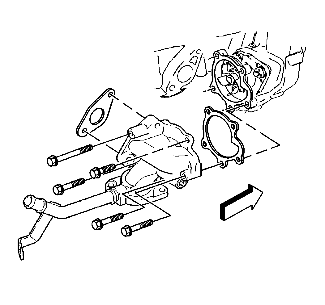
- Remove the water pump cover-to-cylinder block bolts.
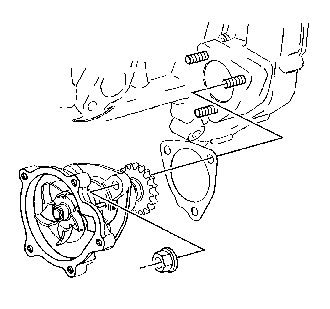
- Remove the 3 water pump-to-timing chain housing nuts.
- Remove the water pump and cover assembly.
- Remove the water pump cover-to-coolant pump assembly bolts.
- Clean all sealing surfaces.
Caution: Unless directed otherwise, the ignition and start switch must be in the OFF or LOCK position, and all electrical loads must be OFF before servicing any electrical component. Disconnect the negative battery cable to prevent an electrical spark should a tool or equipment come in contact with an exposed electrical terminal. Failure to follow these precautions may result in personal injury and/or damage to the vehicle or its components.
Notice: When adding coolant, it is important that you use GM Goodwrench DEX-COOL™ coolant. If coolant other than DEX-COOL™ is added to the system, the engine coolant will require change sooner: at 50 000 km (30,000 miles) or 24 months.

Important: Do not rotate flex coupling more than 4 degrees as damage may occur.
Refer to Exhaust Manifold Replacement in Engine Mechanical - 2.4L.


Installation Procedure
- Install the water pump cover to the water pump assembly.
- Install the pump cover bolts. Hand tighten the bolts.
- Install the cover-to-block bolts. Hand tighten the bolts.
- Install the coolant pump-to-timing chain housing nuts. Hand tighten the nuts.
- Lubricate the O-ring on the coolant inlet pipe with an antifreeze solution.
- Slide the pipe into the water pump cover.
- Install the bolts. Hand tighten the bolts.
- Torque in sequence as follows:
- Install the exhaust manifold and install new gaskets.
- Install the exhaust manifold-to-cylinder head retaining nuts.
- Connect the brake vacuum pipe to the cam housing.
- Raise the vehicle. Refer to Lifting and Jacking the Vehicle in General Information.
- Index the exhaust manifold bolts into the exhaust pipe flange.
- Install the exhaust pipe to the exhaust manifold.
- Install the heater outlet pipe bracket to the transmission.
- Turn exhaust both bolts in evenly in order to avoid cocking the exhaust pipe and binding the bolts. Turn in the bolts until the bolts are fully seated.
- Install the coolant inlet pipe to the oil pan.
- Install the timing chain tensioner.
- Install the timing chain cover.
- Lower the vehicle.
- Install the exhaust manifold brace to the manifold bolt.
- Install the manifold to the exhaust pipe nuts.
- Install the heater hose to the heater pipe.
- Inspect the quick connect retainer. Pull on the heater hose in order to verify the connection.
- Install the upper heat shield to the exhaust manifold.
- Connect the oxygen sensor connector.
- Fill the radiator with coolant.
- Connect the negative battery cable.
- Inspect the system for leaks.
Important: Before you install the coolant pump, read the entire procedure. Follow the tightening sequences in order to avoid part damage and to provide proper sealing.


Notice: Use the correct fastener in the correct location. Replacement fasteners must be the correct part number for that application. Fasteners requiring replacement or fasteners requiring the use of thread locking compound or sealant are identified in the service procedure. Do not use paints, lubricants, or corrosion inhibitors on fasteners or fastener joint surfaces unless specified. These coatings affect fastener torque and joint clamping force and may damage the fastener. Use the correct tightening sequence and specifications when installing fasteners in order to avoid damage to parts and systems.
| 8.1. | Tighten the pump assembly-to-timing chain housing nuts. |
Tighten
Tighten nuts to 26 N·m (19 lb ft).
| 8.2. | Tighten the pump cover-to-pump assembly bolts. |
Tighten
Tighten the bolts to 14 N·m (124 lb in).
| 8.3. | Tighten the coolant pump cover-to-engine block bolts. Tighten the bottom bolt first. |
Tighten
Tighten bolts to 26 N·m (19 lb ft).
| 8.4. | Tighten the coolant inlet pipe assembly-to-coolant pump cover bolts. |
Tighten
Tighten the bolts to 14 N·m (124 lb in).
Refer to Exhaust Manifold Replacement in Engine Mechanical - 2.4L.
Refer to Catalytic Converter Replacement in Engine Exhaust.
Tighten
Tighten nuts to 26 N·m (19 lb ft).
Refer to Camshaft Timing Chain, Sprocket, and Tensioner Replacement in Engine Mechanical - 2.4L.
Refer to Timing Chain Housing Replacement in Engine Mechanical - 2.4L.
Refer to Catalytic Converter Replacement in Exhaust System.
Refer to Cooling System Draining and Filling .
Water Pump Replacement 3.4 L
Removal Procedure
- Disconnect the negative battery cable.
- Drain the cooling system. Recover the coolant. Refer to Cooling System Draining and Filling .
- Remove the drive belt.
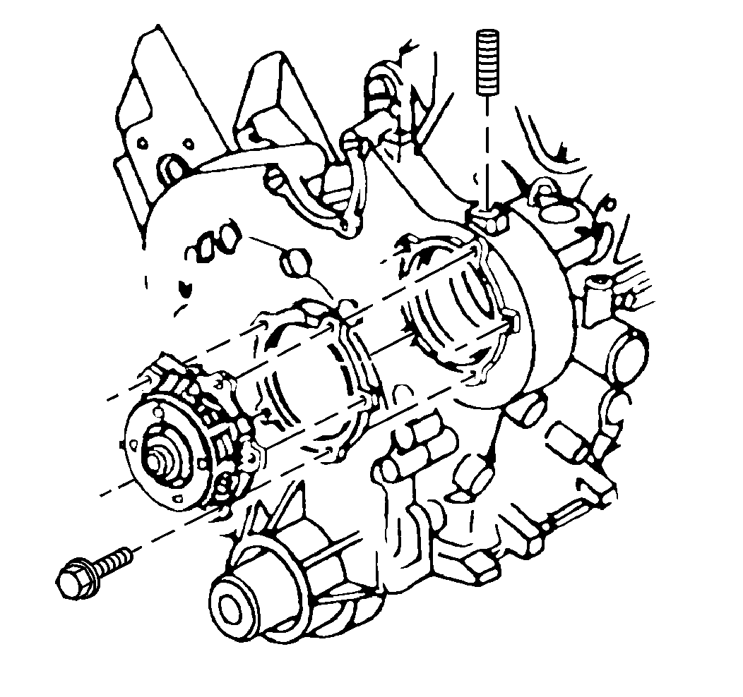
- Remove the water pump pulley bolts.
- Remove the water pump pulley.
- Remove the coolant pump attaching bolts.
- Remove the coolant pump.
- Clean the coolant pump and the sealing surfaces.
Caution: Unless directed otherwise, the ignition and start switch must be in the OFF or LOCK position, and all electrical loads must be OFF before servicing any electrical component. Disconnect the negative battery cable to prevent an electrical spark should a tool or equipment come in contact with an exposed electrical terminal. Failure to follow these precautions may result in personal injury and/or damage to the vehicle or its components.
Notice: When adding coolant, it is important that you use GM Goodwrench DEX-COOL™ coolant. If coolant other than DEX-COOL™ is added to the system, the engine coolant will require change sooner: at 50 000 km (30,000 miles) or 24 months.

Installation Procedure
- Install the water pump and new gasket.
- Install the water pump pulley and the bolts.
- Install the drive belt.
- Tighten the water pump pulley bolts.
- Connect the negative battery cable.
- Refill the cooling system. Refer to Cooling System Draining and Filling .
- Inspect the cooling system for leaks.

Notice: Use the correct fastener in the correct location. Replacement fasteners must be the correct part number for that application. Fasteners requiring replacement or fasteners requiring the use of thread locking compound or sealant are identified in the service procedure. Do not use paints, lubricants, or corrosion inhibitors on fasteners or fastener joint surfaces unless specified. These coatings affect fastener torque and joint clamping force and may damage the fastener. Use the correct tightening sequence and specifications when installing fasteners in order to avoid damage to parts and systems.
Tighten
Tighten the bolts to 10 N·m (89 lb in).
Tighten
Tighten the bolts to 25 N·m (18 lb ft).
Tighten
Tighten the bolts to 16 N·m (12 lb ft).
